Thermally insulated and heated double-walled pipe segment for fitting by screw fastening, and a method of implementing such a pipe segment

a technology of double-walled pipes and screw fastening, which is applied in the direction of screw threaded joints, pipe heating/cooling, manufacturing tools, etc., can solve the problems of thermal insulation defect, increased risk of blockage formation, and inability to heat the pipe, etc., to achieve low electrical power needed for heating, simple assembly, and low cost

Active Publication Date: 2017-11-28
ITP
View PDF20 Cites 2 Cited by
  • Summary
  • Abstract
  • Description
  • Claims
  • Application Information

AI Technical Summary

Benefits of technology

[0038]Another advantage of the present invention lies in the fact that the segments are simple to assemble together, as applies for the existing segments that are described in Patent Document FR-2921996.
[0039]Another advantage of the present invention is that the segments are simple to manufacture.
[0040]Another advantage of the present invention also lies in the fact that it is possible to provide thermal insulation along the entire length of the pipe. Firstly, the electrical power necessary for the heating is low, and secondly the heating energy is supplied uniformly around the periphery of the inner tube and along said inner tube, in particular by means of the heating wires placed under the insulation. The inside temperature of the fluid is thus uniform inside the inner tube.DESCRIPTION OF THE FIGURES
[0041]Other characteristics, advantages, and details of the invention can be better understood on reading the following supplementary

Problems solved by technology

However, any defect in the thermal insulation can cause a cold spot to appear, which then causes a blockage to be formed.
Such a thermal insulation defect can, for example, result from a leak between the outside of the pipe and a portion of the annular space in which the thermal insulation material is then no longer at the reduced pressure, or is even flooded with water coming from the surrounding environment.
The risk of a blockage forming is then increased.
Furthermore, a slight heat loss always occurs towards the outside of the transport pipe.
When the underground deposit is at a low temperature, such slight heat losses may also cause blockages to be formed.
Such slight cooling can also cause a blockage to be formed during production stoppages, during which the fluid being extracted stagnates and cools slowly inside the pipe.
The risk of a blockage forming is then also increased.
Such cleaning of the inner tube causes firstly a production stoppage and secondly maintenance operations that are costly for the operator of the well.

Method used


Image

  • Thermally insulated and heated double-walled pipe segment for fitting by screw fastening, and a method of implementing such a pipe segment
  • Thermally insulated and heated double-walled pipe segment for fitting by screw fastening, and a method of implementing such a pipe segment
  • Thermally insulated and heated double-walled pipe segment for fitting by screw fastening, and a method of implementing such a pipe segment

Examples


Embodiment Construction

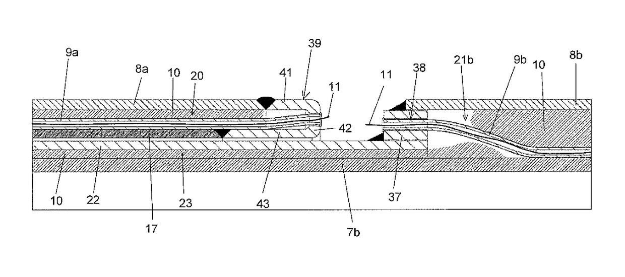
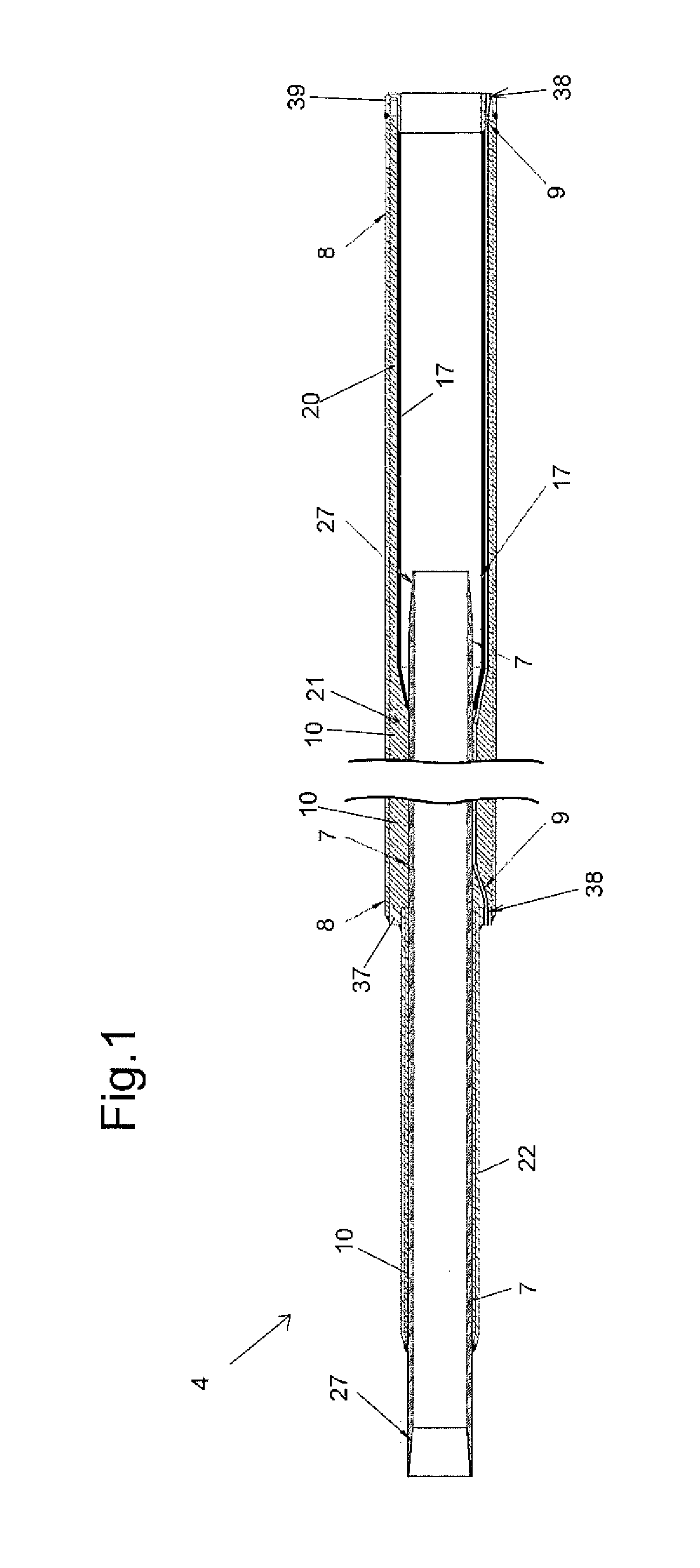
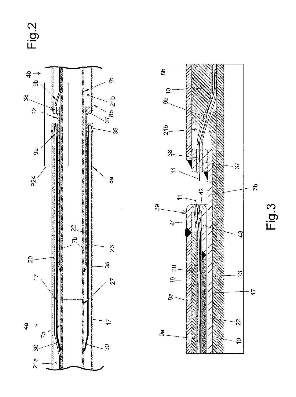
[0054]The invention is described in more detail below. FIG. 1 is a longitudinal section view of a segment 4. For example, a segment may have a length lying in the range 6 meters (m) to 30 m. The segment 4 comprises an inner tube 7 and an outer tube 8, the tubes defining between them an annular space 20 in which a thermal insulation material 10 is placed.

[0055]Each of the ends of the inner tube 7 has thread 27 for assembly to the adjacent segments.

[0056]The segment has a male end portion and a female end portion. Its male end portion is designed to co-operate with a female end portion of an adjacent segment, and its female end portion is designed to co-operate with a male end portion of another adjacent segment.

[0057]The male end portion is constituted by the inner tube 7 projecting relative to the outer tube 8. The outer tube 8 is secured via its end to the inner tube 7 by a closure piece 37 serving to close off the annular space and fastened inside the outer tube 8 to close off the...


PUM

PropertyMeasurementUnit
lengthaaaaaaaaaa
pressureaaaaaaaaaa
pressureaaaaaaaaaa

Abstract

A segment is fitted by screw-fastening for implementing a fluid transport pipe for transporting a fluid, the pipe including an inner wall and an outer wall, the segment including an inner tube and an outer tube that define an annular space between them. The segment includes in particular one heating duct placed in its annular space and opening out at either end of its annular space, the annular space being designed to be closed hermetically in order to enable it to be brought to a reduced pressure. A method of manufacturing the segment and a method of implementing the fluid transport pipe is described.

Description

FIELD OF INVENTION[0001]The present invention relates to the technical field of pipes for transporting fluids, and in particular, pipes for transporting hydrocarbons in wells, such pipes being referred to as “tubing”. The invention relates more particularly to double-walled pipes made up of segments that are screwed together end-to-end.DESCRIPTION OF THE RELATED ART[0002]Double-walled pipes implemented by screwing segments together end-to-end are generally used for wells. A pipe installed in a well can, for example, be disassembled once per year on average. Sometimes, a pumping system is disposed underground, at the end of the pipe, and such a system can then require disassemblies to be performed more often than once per year for servicing and maintenance operations.[0003]U.S. Pat. No. 3,928,903 relates to a method of implementing a double-walled pipe. Each segment of that pipe is manufactured by means of threaded connectors disposed at the ends of the segment to connect its inner t...

Claims


Application Information

Patent Timeline
Patent Type & Authority Patents(United States)
IPC IPC(8): F16L53/00F16L39/00F16L25/01F16L9/18F16L15/00F16L59/14B23P19/00F16L53/35F16L53/38
CPCF16L53/005B23P19/00F16L9/18F16L15/00F16L39/005F16L53/008F16L59/141F16L25/01Y10T29/49964Y10T29/49828F16L53/35F16L53/38F16L9/22F16L15/08F16L53/00
Inventor MARCHAL, PHILIPPEDAMOUR, JEAN-AURELIENOLLIER, PIERRE
Owner ITP
Why Eureka
Try Eureka