System and method for improved reactive power speed-of-response for a wind farm

a technology of reactive power and wind farm, applied in the direction of synchronous generator control, electric generator control, instruments, etc., can solve the problems of local control aggravate voltage flicker, loss of voltage regulation, etc., and achieve the effect of improving the reactive power speed of respons

Active Publication Date: 2017-11-28
GENERAL ELECTRIC CO
View PDF19 Cites 7 Cited by
  • Summary
  • Abstract
  • Description
  • Claims
  • Application Information

AI Technical Summary

Benefits of technology

[0009]In one aspect, the present subject matter is directed to a method for improving reactive power speed-of-response in a wind farm connected to a power grid. The method includes receiving, by a wind farm controller, a voltage feedback from the power grid and a voltage reference. Another step includes calculating a linear voltage error as a function of the voltage feedback and the voltage reference. The method also includes generating a first output based on the linear voltage error via a first control path having a first voltage regulator. Further steps include determining a first non-linear voltage error based on the linear voltage error via a second control path having a second voltage regulator and generating, via the second control path, a second output based on the first non-linear voltage error. The method then includes generating a reactive power command as a function of the first and second outputs.

Problems solved by technology

If the farm-level control is inactive, the local control can aggravate voltage flicker.
This causes the wind turbine generators to encounter limits in steady-state operation that prevent a response to disturbances, thereby resulting in a loss of voltage regulation.

Method used


Image

  • System and method for improved reactive power speed-of-response for a wind farm
  • System and method for improved reactive power speed-of-response for a wind farm
  • System and method for improved reactive power speed-of-response for a wind farm

Examples


Embodiment Construction

[0028]Reference now will be made in detail to embodiments of the invention, one or more examples of which are illustrated in the drawings. Each example is provided by way of explanation of the invention, not limitation of the invention. In fact, it will be apparent to those skilled in the art that various modifications and variations can be made in the present invention without departing from the scope or spirit of the invention. For instance, features illustrated or described as part of one embodiment can be used with another embodiment to yield a still further embodiment. Thus, it is intended that the present invention covers such modifications and variations as come within the scope of the appended claims and their equivalents.

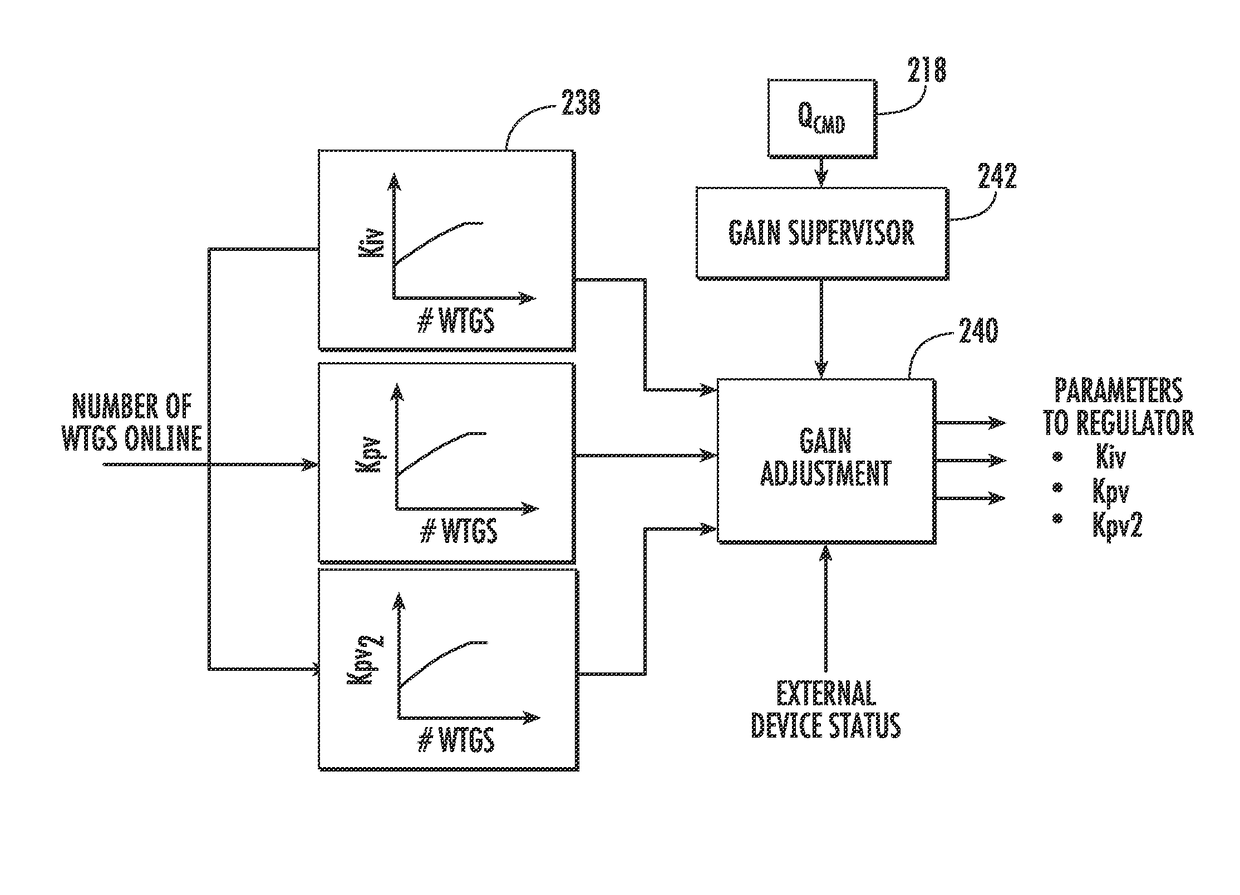
[0029]Generally, the present subject matter is directed to a non-linear farm controller that sends a reactive power command to all of the wind turbine generators within a wind farm or substation. More specifically, the controller includes a non-linear volta...


PUM


Abstract

The present subject matter is directed to a system and method for regulating reactive power in a wind farm connected to a power grid so as to improve reactive speed-of-response of the wind farm. The method includes receiving a voltage feedback from the power grid and a voltage reference and calculating a linear voltage error as a function of the voltage feedback and the voltage reference. A further step includes generating a first output based on the linear voltage error via a first control path having a first voltage regulator. A further step includes determining a non-linear voltage error based on the linear voltage error via a second control path having a second voltage regulator. A second output is generated via the second control path based on the non-linear voltage error. As such, a reactive power command is generated as a function of the first and second outputs.

Description

FIELD OF THE INVENTION[0001]The present disclosure relates generally to wind power generation and, more particularly, to systems and methods for controlling reactive power speed-of-response for a wind farm.BACKGROUND OF THE INVENTION[0002]Wind power is considered one of the cleanest, most environmentally friendly energy sources presently available and wind turbines have gained increased attention in this regard. A modern wind turbine typically includes a tower, a generator, a gearbox, a nacelle, and one or more rotor blades. The rotor blades are the primary elements for converting wind energy into electrical energy. The blades typically have the cross-sectional profile of an airfoil such that, during operation, air flows over the blade producing a pressure difference between its sides. Consequently, a lift force, which is directed from the pressure side towards the suction side, acts on the blade. The lift force generates torque on the main rotor shaft, which is connected to a gener...

Claims


Application Information

Patent Timeline
Patent Type & Authority Patents(United States)
IPC IPC(8): G06F19/00H02P9/00H02J3/38F03D9/25H02J3/18H02P101/15H02P103/20
CPCH02P9/00F03D9/257H02J3/1842H02J3/386Y02E40/22H02P2101/15H02P2103/20Y02E10/763H02J2300/28H02J3/381Y02E10/72Y02E10/76Y02E40/20H02J3/50
Inventor ACHILLES, ALFREDO SEBASTIANLARSEN, EINAR VAUGHN
Owner GENERAL ELECTRIC CO
Why Eureka
Try Eureka