Disposable cap for an eye imaging apparatus and related methods

a technology of eye imaging apparatus and dispensing cap, which is applied in the field of dispensing cap of eye imaging apparatus, can solve problems such as cross-contamination among patients, and achieve the effect of preventing cross-contamination

Inactive Publication Date: 2017-12-26
VISUNEX MEDICAL SYST
View PDF259 Cites 18 Cited by
  • Summary
  • Abstract
  • Description
  • Claims
  • Application Information

AI Technical Summary

Benefits of technology

[0014]In one embodiment, a length of the disposable cap from the distal end to the projection is slightly shorter than a length of a portion of the imaging apparatus from a distal end to a corresponding locking groove. The disposable cap can initiate engagement with the image apparatus when the convex back surface of the window cover touches the front concave surface of the optical window before a latching action to attach the disposable cap takes place. The latching action elongates the shield of the disposable cap, resulting in a pulling force along the axis of the imaging apparatus which helps to secure the disposable cap to the optical window. The slight deformation of the ridge can absorb most of the movement of the cap at the distal end. The ridge does not only match a contour of a corresponding ridge of the imaging apparatus to reduce air between the disposable cap and the imaging apparatus, but more importantly, helps to prevent the optical window cover from bulging and keep the convex back surface of the disposable cap in shape to precisely match the concave surface of the optical window of the imaging apparatus in order to achieve high quality optical performance. The flat ring surface of the disposable cap can act as an alignment reference to ensure that the convex back surface of the disposable cap precisely matches the concave surface of the optical window of the imaging apparatus. The flat ring can also form a supporting pad for the distal ridge. The distal ridge and the flat ring can work together to prevent the convex back surface of the disposable cap from bulging under the pulling force.
[0020]Various embodiments of the disclosure comprise a disposable cap for an eye imaging apparatus with an optical window configured to be in contact with an eye of a patient. The disposable cap can comprise an optical window cover. The optical window cover can comprise a concave surface in a central portion and a side wall in a frusto-conical shape. The optical window cover can be configured to match a contour of a front surface of the optical window. The disposable cap can further comprise a locking element configured to lock the disposable cap to the eye imaging apparatus. The disposable cap can be configured to be able to easily attach to and detach from the eye imaging apparatus. In some embodiments, the disposable cap can further comprise a shield connected with the optical window cover. The locking element can be disposed on the shield. In one embodiment, the locking element can comprise one or more locking projections. In another embodiment, the disposable cap can comprise a locking ring. In some embodiments, the disposable cap can further comprise one or more releasing tabs, configured to release the disposable cap from the imaging apparatus. In some embodiment, the shield of the disposable cap can further comprise a spring style structure to allow the flexibility and elongation of the shield during the process of attaching the disposable cap to and detaching the disposable cap from the eye imaging apparatus.
[0025]Various embodiments disclosed herein comprise a method of preventing cross-contamination caused by an eye imaging apparatus. The eye imaging apparatus can have an optical window configured to be in contact with an eye of a patient and at least one locking groove. The method can comprise disposing an index matching gel to a front surface of the optical window. The method can further comprise attaching a disposable cap to the eye imaging apparatus. The disposable cap can comprise an optical window cover with a concave surface configured to match a contour of the front surface of the optical window and a locking element. The method comprises moving the disposable cap until the locking element and the at least one locking groove mate and lock the disposable cap to the eye imaging apparatus. The method also comprises capturing an image of the eye using the imaging apparatus. The method further comprises detaching the disposable cap from the eye imaging apparatus, and disposing of the disposable cap.
[0026]Various embodiments of the disclosure comprise a method of preventing cross-contamination caused by an eye imaging apparatus by using a disposable system. The eye imaging apparatus can comprise an optical window. The optical window can be configured to be in contact with an eye of a patient. The disposable system can comprise a disposable cap and a disposable packaging shell where the disposable cap is disposed inside the disposable packaging shell. The disposable cap can comprise an optical window cover with a concave surface configured to match a contour of the front surface of the optical window. The disposable packaging shell can comprise a sealing lid, a concave indentation configured to support the optical window cover. The method comprises disposing an index matching gel to a front surface of the optical window of the eye imaging apparatus. The method can comprise opening the sealing lid of the disposable packaging shell. The method also comprises placing the disposable packaging shell with the disposable cap over the eye imaging apparatus. The method further comprises moving the disposable packaging shell with the disposable cap to lock the disposable cap to the eye imaging apparatus. The method can comprise pulling the eye imaging apparatus with the disposable cap out of the disposable packaging shell. The method further comprises applying the index matching gel to a cornea of the eye, and contacting the cornea with the disposable cap. The method can comprise capturing an image of the eye by using the eye imaging apparatus. The method further comprises placing the eye imaging apparatus with the disposable cap back into the disposable packaging shell, and moving the disposable packaging shell to lock the disposable cap to the packaging shell. The method can comprise pulling the eye imaging apparatus out of the disposable cap and leaving the disposable cover inside the packaging shell. The method can comprise disposing of the disposable packaging shell with the disposable cap.

Problems solved by technology

An eye imaging apparatus with an optical window in direct contact with a cornea of an eye of the patients can potentially cause cross-contamination among patients.

Method used


Image

  • Disposable cap for an eye imaging apparatus and related methods
  • Disposable cap for an eye imaging apparatus and related methods
  • Disposable cap for an eye imaging apparatus and related methods

Examples


Embodiment Construction

[0068]Various aspects of the present disclosure now will be described in detail with reference to the accompanying figures. These aspects of the disclosure may be embodied in many different forms and should not be construed as limited to the exemplary embodiments discussed herein.

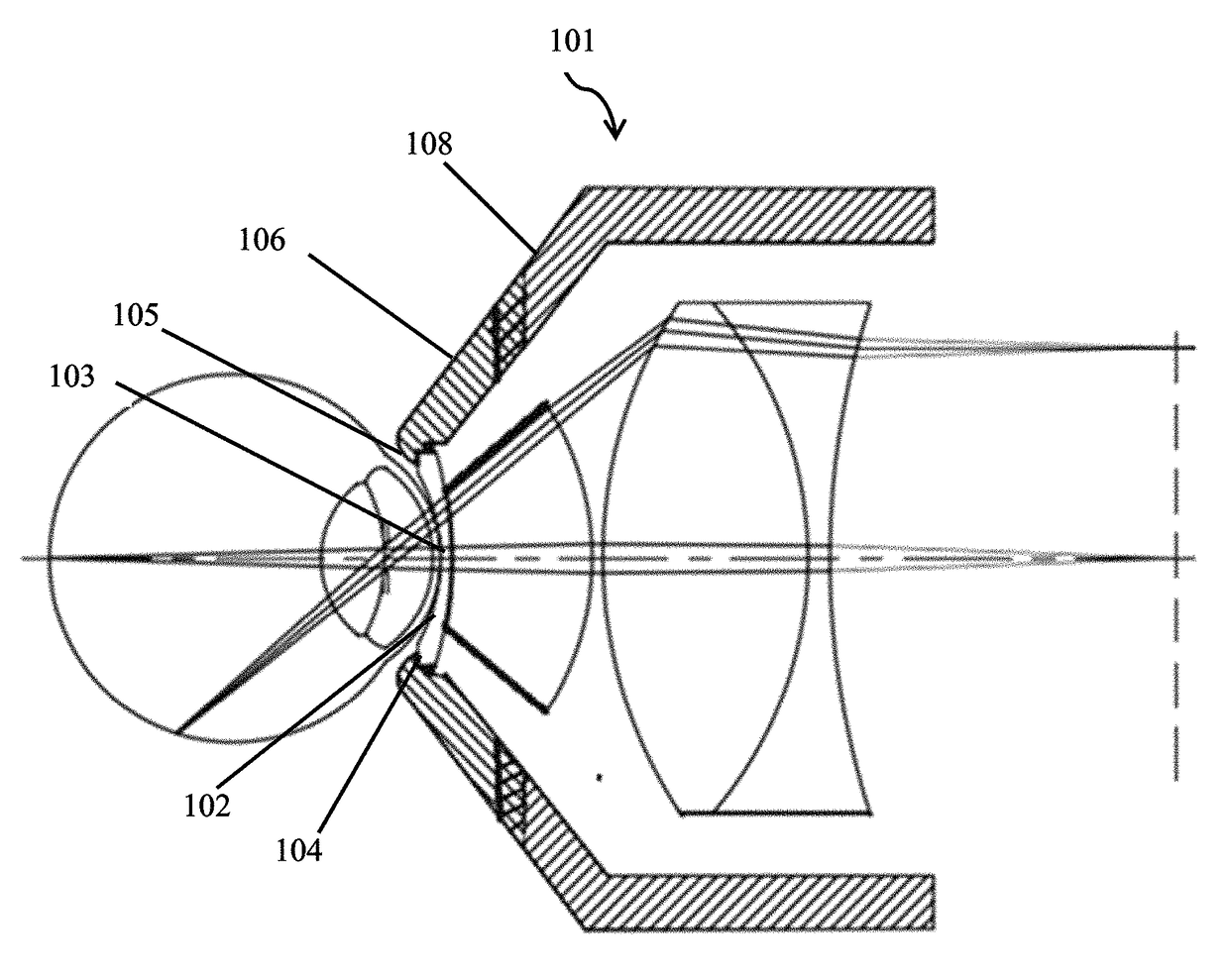
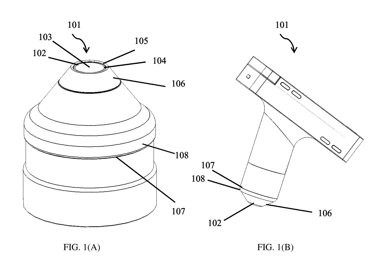
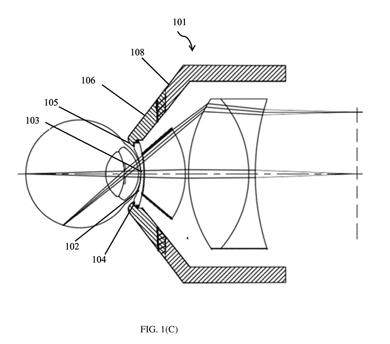
[0069]Various embodiments of the present disclosure describe a disposable cap for a medical imaging apparatus, for example, an eye imaging apparatus. The disposable cap may be single use and sterile, which can provide a physical barrier between the imaging apparatus and the patients where the imaging apparatus has to be in direct contact with the patients during medical examination or operation. The disposable cap can be manufactured and individually placed into a sealed disposable packaging shell with air-tight sealing in a sterilized environment. The disposable cap can be exposed to Gamma ray or E-beam during the radiation sterilization process or other sterilization processes per FDA requirements. Before...


PUM


Abstract

Disclosed herein is a disposable cap for an eye imaging apparatus with an optical window and related methods. The disposable cap can comprise an optically transparent window cover, a ridge, a side wall and a locking element. The window cover can comprise a convex back surface to match a concave shape of the optical window. The ridge of the disposable cap can extend distally and radially outward from the window cover and the side wall can extend proximally and radially outwardly from the ridge. The locking element can comprise one or more radially inward projections and one or more radially outward releasing tabs. A disposable packaging shell of the disposable cap also disclosed. Disclosed herein is also a plug-in disposable system comprising the disposable cap and the disposable packaging shell, configured to enable the disposable cap to be attached to and detached from the eye imaging apparatus.

Description

CROSS REFERENCE TO RELATED APPLICATIONS[0001]This application claims the benefit of U.S. Provisional Application No. 62 / 107,993, filed Jan. 26, 2015, which is herein incorporated by reference in its entirety.INCORPORATION BY REFERENCE[0002]All publications and patent applications mentioned in this specification are incorporated herein by reference in their entirety to the same extent as if each individual publication or patent application was specifically and individually indicated to be incorporated by reference, including: U.S. Pat. No. 9,155,466, titled “EYE IMAGING APPARATUS WITH A WIDE FIELD OF VIEW AND RELATED METHODS”, filed on Feb. 4, 2015, which is a continuation of U.S. application Ser. No. 14 / 191,291 filed Feb. 26, 2014, which is a continuation-in-part of U.S. Pat. No. 9,179,840, titled “IMAGING AND LIGHTING OPTICS OF A CONTACT EYE CAMERA”, filed on Mar. 17, 2013 which claims the benefit of U.S. Provisional Application No. 61 / 612,306 filed on Mar. 17, 2012, and U.S. paten...

Claims


Application Information

Patent Timeline
Patent Type & Authority Patents(United States)
IPC IPC(8): A61B3/00A61B3/125A61B3/15A61B50/30A61B46/10A61B50/00A61B17/00
CPCA61B3/125A61B3/15A61B46/10A61B50/30A61B2017/00902A61B2050/3015A61B2050/0051A61B2050/0054A61B2050/0066A61B2050/0084A61B2050/005
Inventor SU, WEI
Owner VISUNEX MEDICAL SYST
Why Eureka
Try Eureka