
Drilling safety system

a safety system and drill bit technology, applied in the direction of manufacturing tools, metal-working machine components, transportation and packaging, etc., can solve the problems of switchgear damage, particularly dangerous drill bit, etc., and achieve the effect of easy manufacturing

Active Publication Date: 2017-12-26
BIALY CHRISTOPHER R +1
View PDF70 Cites 6 Cited by
  • Summary
  • Abstract
  • Description
  • Claims
  • Application Information

AI Technical Summary

Benefits of technology

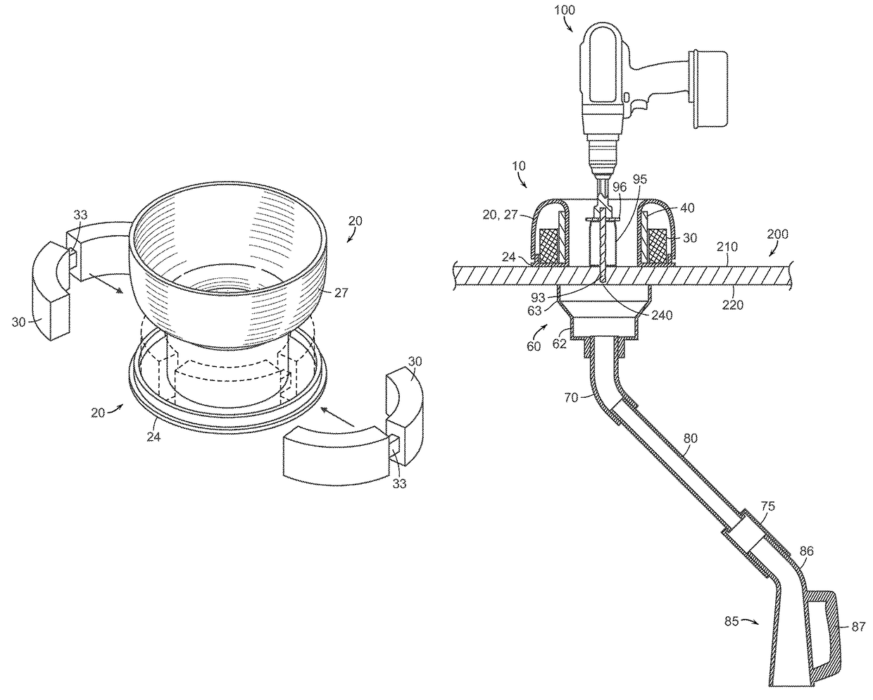
[0011]Before drilling starts, the magnetic unit is placed on the drilling surface, and around and / or adjacent to the drilling site. In a preferred embodiment, the magnetic unit has a ring or annulus shape, allowing it to surround the drilling site. The cover of the magnetic unit may comprise a unit base and a flippable top; the magnet core may be placed on the unit base; and the flippable top may be flipped up to allow the magnet core to be removed. During drilling, the metal shavings on the drilling surface are pulled towards the magnetic unit and attach to the cover, which is preferably non-magnetic and non-conductive. After drilling, the flippable top is flipped up, allowing the magnet core to be removed so that the metal shavings can no longer attach to the cover. The user may then easily discard the shavings. To ensure the physical robustness of the magnetic unit, a support structure may be included to provide physical support to the magnetic unit.
[0028]It is a further object of the invention to provide a drill safety system that is easy to manufacture.

Problems solved by technology

Such shavings are particularly dangerous because equipment such as switchgear may be damaged if the shavings fall into the equipment.

Method used


Image

  • Drilling safety system
  • Drilling safety system
  • Drilling safety system

Examples


Embodiment Construction

[0037]The preferred embodiments of the present invention will now be described with reference to the drawings. Identical elements in the various figures are identified, as far as possible, with the same reference numerals. Reference will be made in detail to embodiments of the present invention. Such embodiments are provided by way of explanation of the present invention, which is not intended to be limited thereto. In fact, those of ordinary skill in the art may appreciate upon reading the present specification and viewing the present drawings that various modifications and variations can be made thereto without deviating from the innovative concepts of the invention.

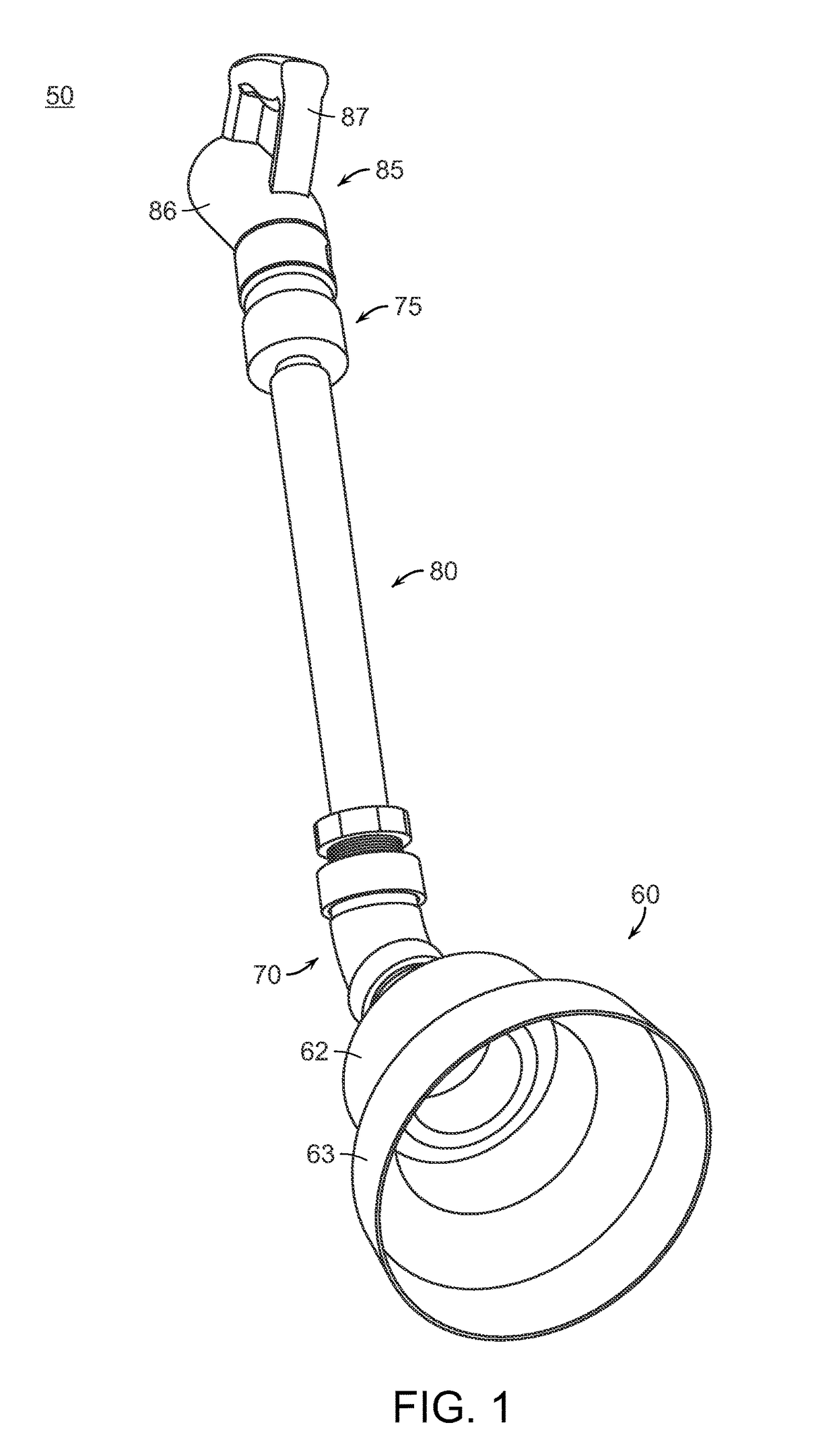
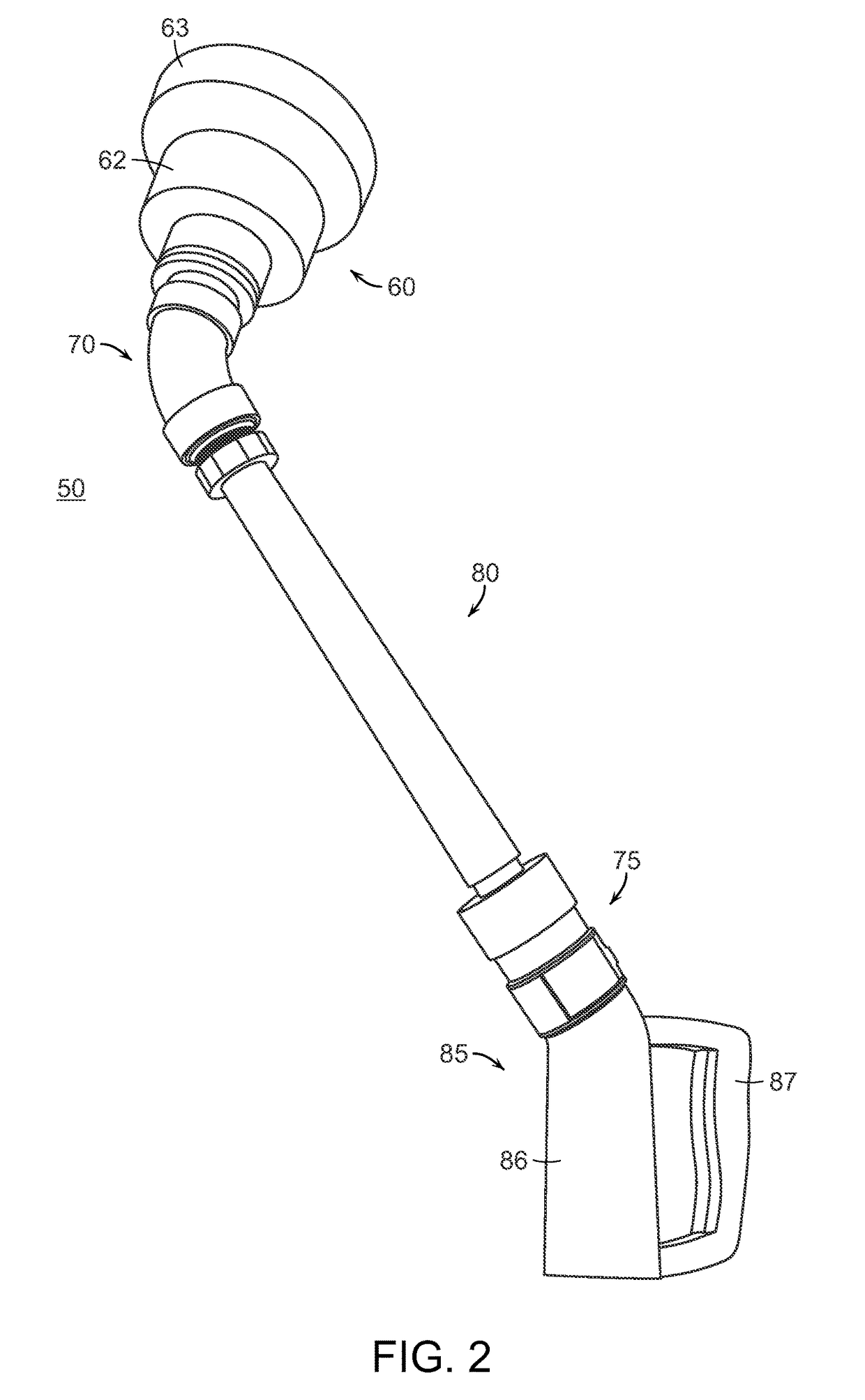
[0038]FIG. 1 shows a top perspective view of a vacuum unit of the drill safety system. Shown in FIG. 1 is the vacuum unit 50 having a collecting cup 60, a first connector 70, a second connector 75, a connecting tube 80, and a handle element 85, wherein the collection cup 60 has a lower cup body 62 and an enlarged cup r...


PUM

PropertyMeasurementUnit
areaaaaaaaaaaa
areaaaaaaaaaaa
lengthaaaaaaaaaa

Abstract

The present disclosure describes and teaches a drill safety system including a magnetic unit, a vacuum unit, and an improved hole saw drill set. The various parts of the drill safety system may be used individually or in combination with one another. The user may use the magnetic unit to surround the drilling site so that metal drill shavings on the drill surface may be collected by the magnetic unit. In addition, the magnetic unit includes a flippable top mechanism, allowing convenient disposal of the debris. The vacuum unit is fitted to the inner surface of the drilling site, collecting debris that fall through. The improved hole saw prevents over-penetrating by the drill, reducing the likelihood of damaging equipments underneath the drill site. This makes the drill particularly suitable for drilling holes during electrical work.

Description

CLAIM OF PRIORITY[0001]This application claims the priority of U.S. Ser. No. 61 / 777,635 filed on Mar. 12, 2013, the contents of which are fully incorporated herein by reference.FIELD OF THE INVENTION[0002]The invention relates to a drilling safety system and more particularly relates to a safety system specially designed to prevent drill shaving and debris from damaging the surrounding equipments and harming the worker.BACKGROUND OF THE INVENTION[0003]For many manufacturing, maintenance, and repair projects, drilling is an indispensible part of the operation. Under some circumstances, drilling can become hazardous to the person conducting the drilling, the workpiece, and / or the equipments and environment surrounding the drilling site. If essential safety devices cannot be provided, or if proper safety procedures cannot be followed, accidents during drilling may happen, causing significant damages and threatening the worker's wellbeing.[0004]One example for hazardous drilling operati...

Claims


Application Information

Patent Timeline
Patent Type & Authority Patents(United States)
IPC IPC(8): B23Q11/00B23B47/34B23B51/04
CPCB23Q11/0064B23B47/34B23Q11/0046Y10T408/895Y10T408/50Y10T408/554B23B51/0406B23B51/04
Inventor BIALY, CHRISTOPHER R.VROMAN, JR., RICHARD C.
Owner BIALY CHRISTOPHER R
Learn More