Apparatus for generating a line-beam from a diode-laser array

Active Publication Date: 2017-12-26
COHERENT INC
View PDF6 Cites 7 Cited by
  • Summary
  • Abstract
  • Description
  • Claims
  • Application Information

AI Technical Summary

Benefits of technology

The present invention provides a line-beam generating apparatus that includes a diode-laser bar emitting laser-radiation in an emission direction. The apparatus includes a collimating lens, a focusing lens, and a linear micro-lens array. The linear micro-lens array has a plurality of cylindrical micro-lenses arranged in an elongated array. The apparatus is designed to form a line-beam in a first illumination plane from the laser-radiation emitted by the diode-laser bar. The apparatus also includes a spherical lens for projecting an image of the partially-blocked line-beam in a second illumination plane to a third illumination plane. The technical effects of the present invention include improved line-beam generation and improved image quality.

Problems solved by technology

However, soldering a relatively-thin diode-laser bar onto a rigid cooling base causes mechanical stress that can displace the diode-laser emitters from an ideal linear alignment.
However, additional metrology and reduced yield increase cost.
However, soft solders are more vulnerable to failure, due to atomic diffusion and oxidation.
However, such schemes add cost and complexity to packaging.
However, it is necessary to overcome an inherent non-uniformity of emission from a plurality of spatially-distributed diode-laser emitters.
However, line-beams created by such devices are degraded by smile.
While prior-art devices can create a uniform line-beam at one location along a transformed beam, they are unable to provide uniform illumination along a range of locations.

Method used


Image

  • Apparatus for generating a line-beam from a diode-laser array
  • Apparatus for generating a line-beam from a diode-laser array
  • Apparatus for generating a line-beam from a diode-laser array

Examples


Embodiment Construction

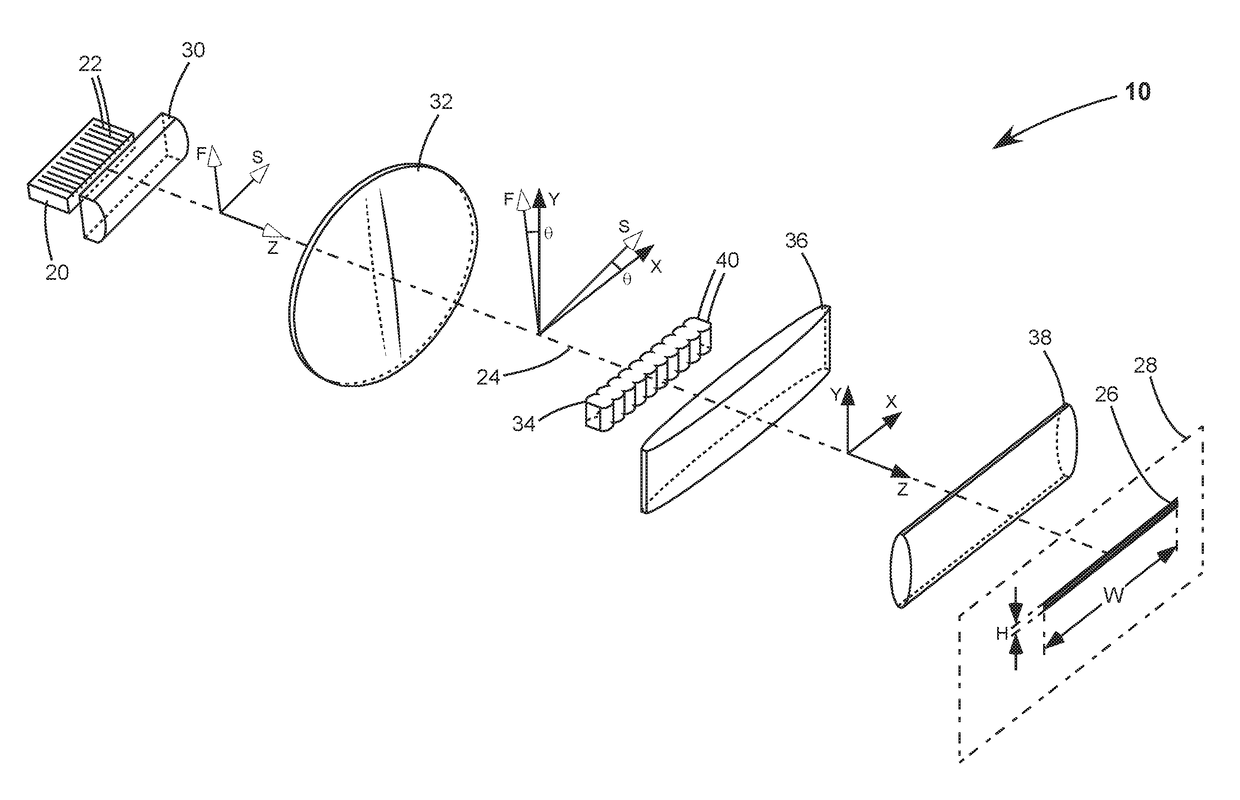
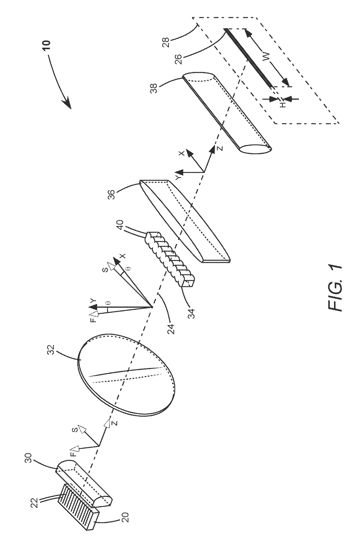
[0029]Turning now to the drawings, wherein like features are designated by like reference numerals, FIG. 1 schematically illustrates one preferred embodiment 10 of line-beam generating apparatus in accordance with the present invention. Apparatus 10 comprises a diode-laser bar 20 and a plurality of optical components described further herein below. Diode-laser bar 20 has characteristic slow-axis “S”, fast-axis “F”, and emission “Z” directions, as indicated in the drawing. Diode-laser bar 20 has a plurality of diode-laser emitters 22 arranged in a linear array thereof, parallel with the slow-axis direction. The optical components are arranged along an optical axis 24 that is co-linear with the emission direction. Diode-laser bar 20 and the optical components are arranged to shape laser-radiation emitted by the diode-laser bar to form an elongated line-beam 26 in an illumination plane 28 that is perpendicular to optical axis 24.

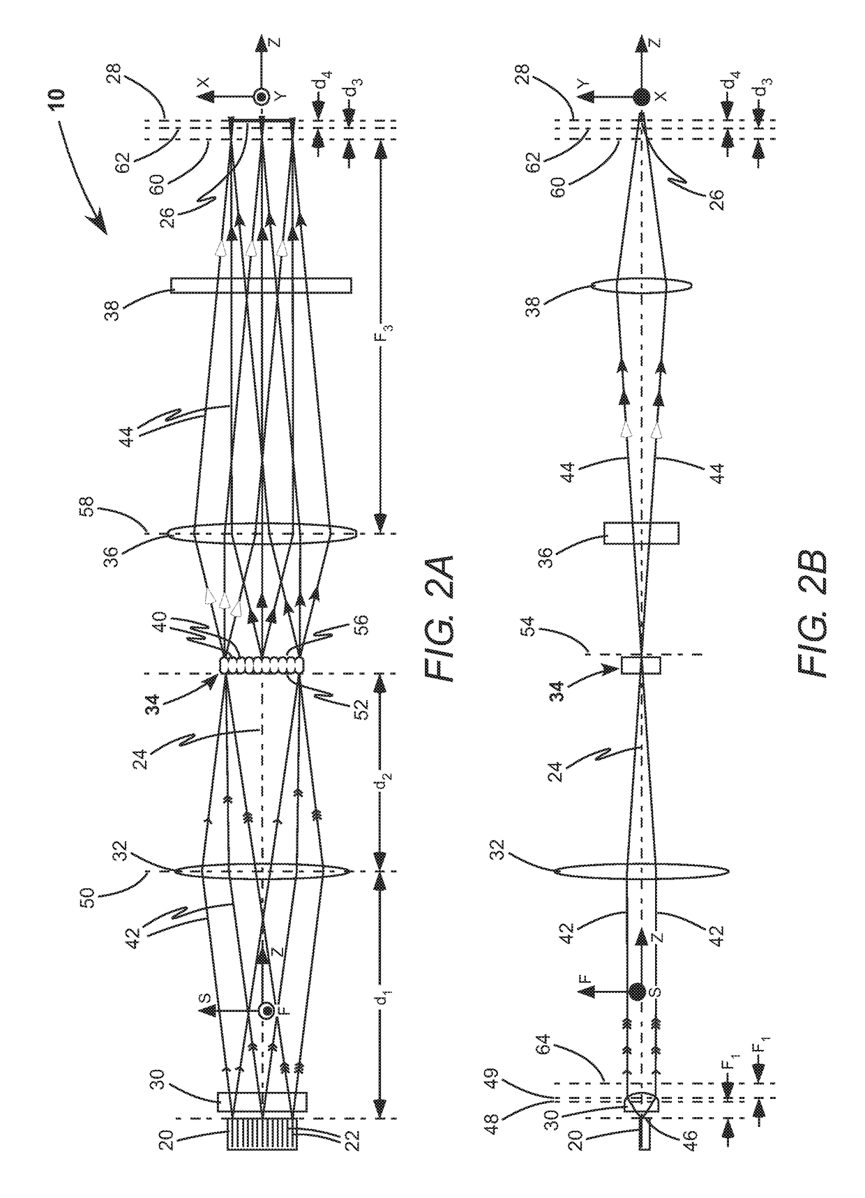
[0030]The optical components are, in order along the emis...


PUM


Abstract

Apparatus for generating a line-beam includes a diode-laser bar, a linear micro-lens array, and a plurality of lenses spaced apart and arranged along an optical axis. The linear micro-lens array and the lenses shape laser-radiation emitted by the diode-laser bar to form a uniform line-beam in an illumination plane. The lenses project a far-field image of the diode-laser bar onto an image plane proximate to the illumination plane. The diode-laser bar is rotated from parallel alignment with the linear micro-lens array for providing uniform line-beam illumination over a range of locations along the optical axis.

Description

PRIORITY[0001]This application claims priority to U.S. Provisional Patent Application Ser. No. 62 / 368,078, filed on Jul. 28, 2016, the entire disclosure of which is incorporated herein by reference.TECHNICAL FIELD OF THE INVENTION[0002]The present invention relates in general to shaping light from diode-lasers. It relates in particular to shaping light from an array of diode-laser emitters into a beam of radiation having a uniform elongated cross section.DISCUSSION OF BACKGROUND ART[0003]Diode-lasers are efficient devices for converting electrical power into coherent optical power. An edge-emitting diode-laser has a diode-laser emitter, which is waveguide resonator, grown on a single-crystal substrate. The diode-laser emitter emits laser-radiation through an end facet in an emission direction. The diode-laser emitter is typically between 500 micrometers (μm) and 2,000 μm long, between 40 μm and 200 μm wide, and about 1 μm high. The laser-radiation is weakly divergent in a slow-axis ...

Claims


Application Information

Patent Timeline
IPC IPC(8): H01S3/08G02B27/20G02B27/09G02B27/30
CPCG02B27/0961G02B27/30G02B27/0966G02B27/0927G02B19/0057G02B19/0014H01S5/4012H01S5/4031H01S2301/20H01S5/4025
Inventor ZHANG, RUICAPRARA, ANDREA
Owner COHERENT INC
Why Eureka
Try Eureka