
Rolling type vehicle

a technology of rolling type and vehicle, which is applied in the direction of deflectable wheel steering, bicycles, transportation and packaging, etc., can solve the problem of difficulty in reducing the spacing between the left and right front wheels (vehicle width) of the rolling type vehicl

Inactive Publication Date: 2018-01-02
HONDA MOTOR CO LTD
View PDF17 Cites 6 Cited by
  • Summary
  • Abstract
  • Description
  • Claims
  • Application Information

AI Technical Summary

Benefits of technology

[0007]Accordingly, it is an object of an embodiment of the present invention to make or keep small the spacing between left and right front wheels while providing an actuator for controlling the inclination angle of a vehicle body, in a rolling type vehicle which has a pair of left and right front wheels and in which a vehicle body is capable of rolling.
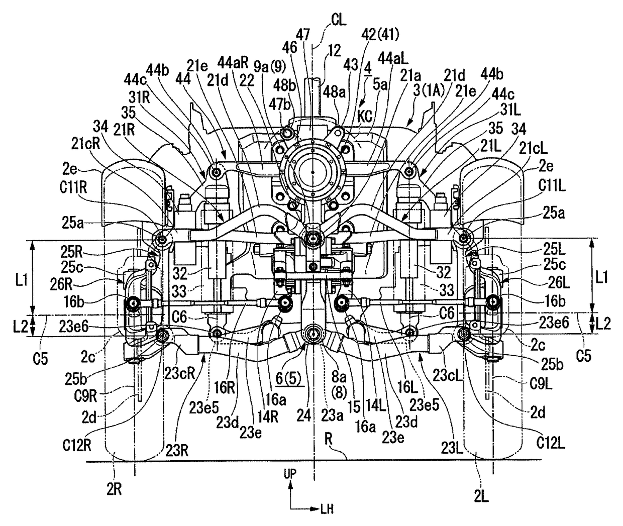
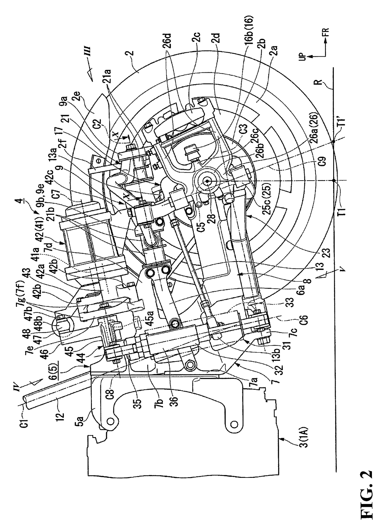
[0013]According to an embodiment of the present invention, the actuator is configured as part of the front suspension frame body of a closed structure and is brought into lateral swinging, or rolling, together with the vehicle body. By this it is ensured that the actuator and the front suspension frame body do not interfere with each other at the time of rolling of the vehicle body. In addition, a swinging space for the front suspension frame body can be utilized as a swinging space for the actuator, so that interference thereof with the surrounding component parts can be inhibited. In addition, since the front suspension frame body is divided into the vehicle body side frame and the actuator, productivity and processibility of the individual configurations can be enhanced. Further, by configuring the front suspension frame body in a closed loop form, a reduction in weight and enhancement of rigidity can be realized, and the spacing between the left and right front wheels (vehicle width) can be made or kept small by, for example, rendering the front suspension frame body compact.
[0014]According to an embodiment of the present invention, the actuator can be disposed at such a position as not to interfere with the left and right arm members. In addition, it is possible to enhance the degree of freedom in laying out the left and right arm members, thereby realizing a smaller vehicle width.
[0015]According to an embodiment of the present invention, the upper arms are supported in the upper opening portion which opens to the upper side. Therefore, the upper arms can be easily mounted or assembled onto the vehicle body side frame, so that workability is enhanced. In addition, since the actuator constitutes an upper part of the front suspension frame body of a closed loop form, the actuator can be disposed apart from and be restrained from interfering with the vehicle body side frame and the surrounding component parts. In addition, the actuator is disposed so as to straddle and close the opening portion upwardly of the opening portion and is connected to the vehicle body side frame. Therefore, both end portions of the actuator which are located on opposite sides of the opening portion can be connected to and firmly supported by the vehicle body side frame. Consequently, the actuator can be restrained from shaking and vibration.
[0016]According to an embodiment of the present invention, the actuator is supported on the vehicle body side frame at a position similar to those of the rear base portions of the upper arms. Owing to this configuration, the actuator is restrained from protruding forward. Thus, a compact front suspension frame body can be realized. In addition, the actuator being heavy can be disposed closer to the center of the vehicle body, whereby mass concentration can be achieved.
[0017]According to an embodiment of the present invention, an output portion of the actuator and a shaft support portion of the shock absorber support arm can be connected coaxially with each other. Consequently, swinging of the shock absorber support arm can be controlled by the actuator while adopting a simple and compact mechanism.

Problems solved by technology

This point constitutes one of the causes which make it difficult to reduce the spacing between the left and right front wheels (vehicle width) of the rolling type vehicle.

Method used


Image

  • Rolling type vehicle
  • Rolling type vehicle
  • Rolling type vehicle

Examples


Embodiment Construction

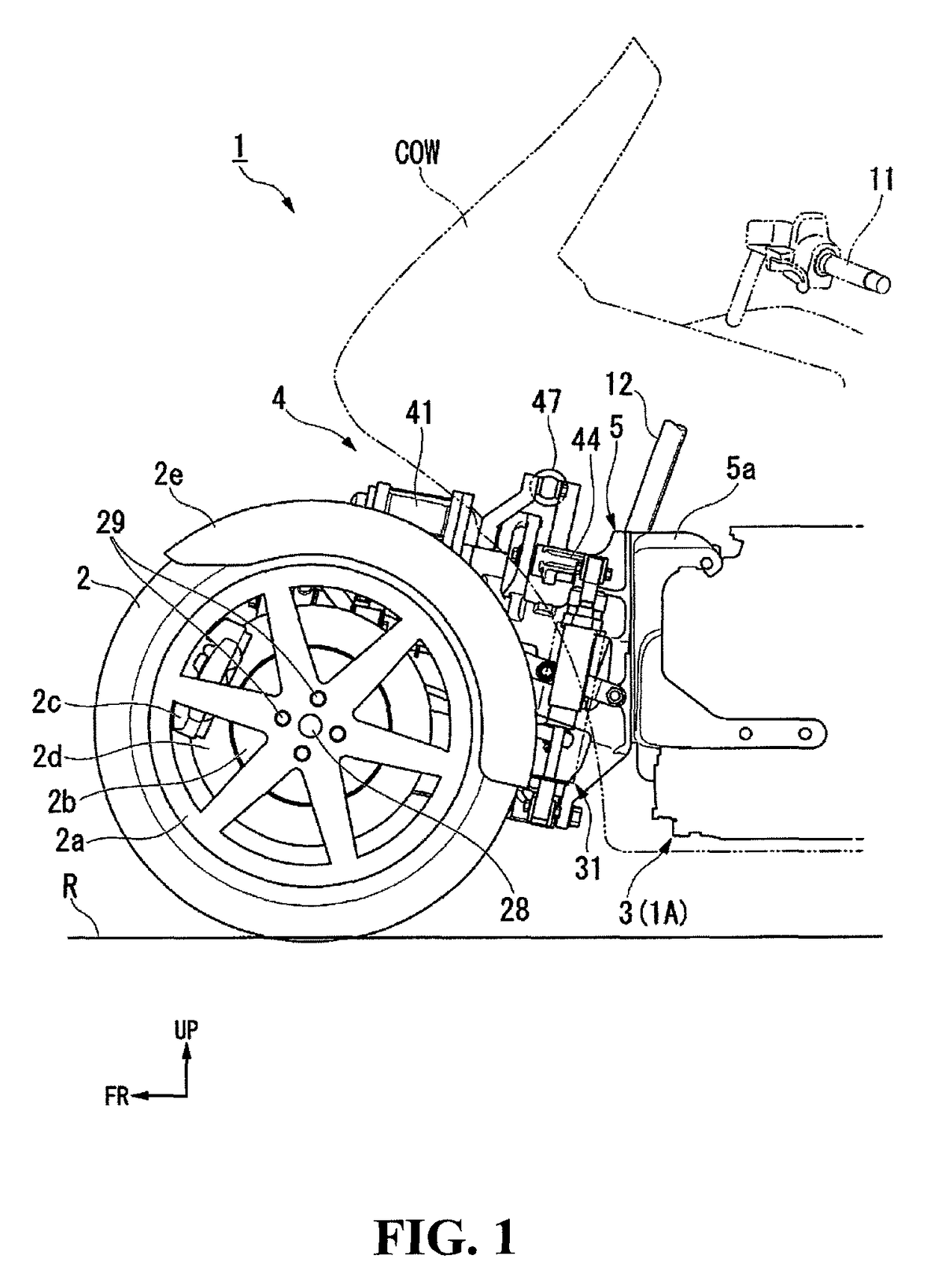
[0037]An embodiment of the present invention will be described below, referring to the drawings. It is to be noted that the directions such as forward, rearward, leftward and rightward directions in the following description are the same as those directions with reference to a vehicle described hereinbelow, unless otherwise specified. In addition, at appropriate locations in the drawings used in the following description, there are shown an arrow FR indicative of the front side of the vehicle, an arrow LH indicative of the left-hand side of the vehicle, and an arrow UP indicative of the upper side of the vehicle. In addition, line CL in the drawings is a longitudinally extending vehicle body center line.

[0038]FIG. 1 shows a vehicle body front portion of a saddle type vehicle 1 in the present embodiment. The saddle type vehicle 1 is a two-front-wheeled three-wheel rolling type vehicle which includes a pair of left and right front wheels (steered wheels) 2 in left-right symmetry at ve...


PUM


Abstract

In a rolling type vehicle including a pair of left and right front wheels wherein a vehicle body is capable of rolling, the spacing between left and right front wheels is maintained as a small spacing while providing an actuator for controlling the inclination angle (lean angle) of a vehicle body. The rolling type vehicle includes left and right upper arms, and lower arms for supporting the left and right front wheels on the vehicle body with a shock absorber support arm swingably supported by the vehicle body and connected to the left and right lower arms through shock absorber units. An actuator is capable of controlling the swinging of the shock absorber support arm. The actuator forms a front suspension frame body of a closed structure together with a vehicle body side frame.

Description

CROSS-REFERENCE TO RELATED APPLICATIONS[0001]The present application claims priority under 35 USC 119 to Japanese Patent Application No. 2015-024458 filed Feb. 10, 2015 the entire contents of which are hereby incorporated by reference.BACKGROUND OF THE INVENTION[0002]1. Field of the Invention[0003]The present invention relates to a rolling type vehicle.[0004]2. Description of Background Art[0005]A rolling type vehicle is known that includes a pair of left and right front wheels wherein a vehicle body is capable of lateral swinging, or rolling. One rolling type vehicle is known that has an actuator for controlling the inclination angle (lean angle) of a vehicle body. See, for example, U.S. Pat. No. 8,123,240.[0006]In the rolling type vehicle mentioned above, the actuator should be laid out in such a position so as not to interfere with arm members which support left and right front wheels, a suspension frame which supports the arm members, or the like. This point constitutes one of t...

Claims


Application Information

Patent Timeline
Patent Type & Authority Patents(United States)
IPC IPC(8): B60G3/26B62K5/10B62K5/08B62K5/01B62K5/027B62D9/02B62K5/00
CPCB60G3/26B62D9/02B62K5/01B62K5/027B62K5/10B62K5/08B62K2207/02B62K2005/001B60G2500/40B62J45/4151
Inventor MORI, YOTARO
Owner HONDA MOTOR CO LTD
Learn More