Dome structure

a dome and structure technology, applied in the field of civil engineering, can solve problems such as impracticality in application

Active Publication Date: 2018-01-02
PISSETTI CASSIO
View PDF13 Cites 1 Cited by
  • Summary
  • Abstract
  • Description
  • Claims
  • Application Information

AI Technical Summary

Problems solved by technology

However in the current art there is no system which provides use and installation in a linear form and non-point, so that natural light is distributed more homogeneously in the environment without transmitting heat to the inner environment.
It is also known of the use of double lenses in the exterior, but only in individual and point module, non-linear, whose in-line mounting in building covers makes it quite expensive, because of the construction characteristics of the said module, making it application impractical.

Method used


Image

  • Dome structure
  • Dome structure
  • Dome structure

Examples


Embodiment Construction

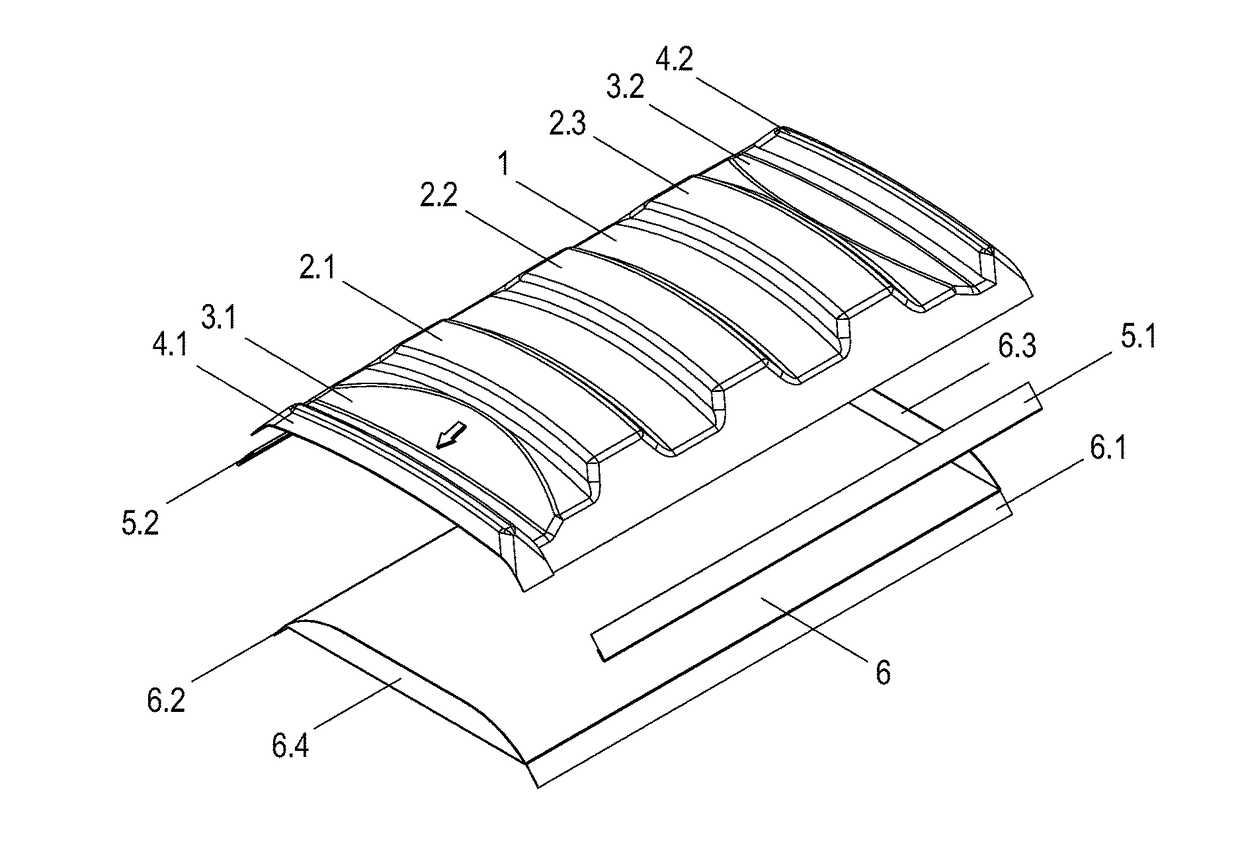
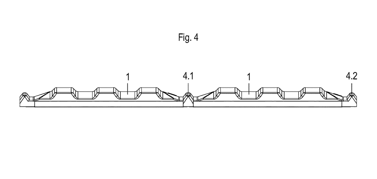
[0015]According to FIG. 1, the dome (1) in question is preferably curvilinear, substantially has a rectangular shape and is optionally provided with three cavities in parallelepiped protuberance (2.1, 2.2 and 2.3), trimmings (3.1 and 3.2) for finishing, horizontal transversal flanges (4.1 and 4.2) at both ends, longitudinal profiles (5.1, 5.2) preferentially “U” orthogonal and glass plate (6) positioned in the lower section of said dome, with said plate comprising longitudinal sealing flaps (6.1 and 6.2) and transverse sealing tabs (6.3 and 6.4).

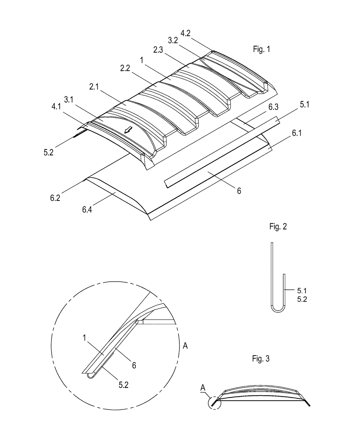
[0016]According to FIGS. 2 and 3, the longitudinal profiles (5.1, 5.2) are made of metallic material and dimensioned in length to have a longitudinal extent of the dome. Such longitudinal profiles (5.1 and 5.2) are responsible for linking the dome (1) and the crystal plate (6) by pressure method, gluing, screwing, among other methods, to give a double lens (double glazing) in the bottom point of said dome (1), causing the day light apparatus...


PUM


Abstract

The invention is related to the field of civil engineering, particularly related to the translucent roofs of buildings, and regards the production of polycarbonate dome structure or translucent material, made of double lens and tube formation, which allows the installation and mounting of the same in-line, in the roofing structures, targeting design and extending day light in the inner area of buildings, even at low climatic condition, reducing the passage of excessive heat into the environment to be illuminated. In addition to reducing heat passage by approximately 30%, its use installation will take place linearly and non-point, so that natural light is distributed more homogeneously in the environment. The material for its manufacture can come from prismatic polycarbonate, acrylic or other compatible material and its manufacturing process adopts vacuum system forming (thermoforming).

Description

TECHNICAL FIELD[0001]The present invention relates to the field of civil engineering, particularly related to translucent covers for buildings, and concerns the production of a polycarbonate dome assembly, consisting of double lenses and tube formation, which allows the installation and assembly in line, in the roofing structures, targeting design and to extend day light in the inner area of buildings, even at low climatic condition, reducing the passage of excessive heat into the environment to be illuminated.BACKGROUND OF THE INVENTION[0002]In civil construction, roofing in general are commonly used to provide protection from the sun or rain for commercial and industrial environments. These constructs can be composed of different structures and materials, using commonly precast concrete or steel for the assembly of base and different materials for the cover from heavier materials such as metal alloys, concrete tiles, to lighter materials as plastic, thin metal alloys and polycarbo...

Claims


Application Information

Patent Timeline
Patent Type & Authority Patents(United States)
IPC IPC(8): E04B7/18E04D13/03E06B3/66E06B3/673E04B7/08E04B7/10
CPCE04D13/0305E04D13/032E06B3/66E06B3/673E04B7/08E04B7/10E04B7/102
Inventor PISSETTI, CASSIO
Owner PISSETTI CASSIO
Why Eureka
Try Eureka