Holding device for screw energy-saving lamp tube formation

A clamping device and energy-saving lamp technology, which is applied in glass forming, glass reshaping, manufacturing of ships or leading wires, etc. It can solve the problems of poor consistency of glass tubes, affecting the pass rate and quality of glass tubes, and poor working conditions, etc. problem, to achieve the effect of good air tightness, simple structure and low production cost

Inactive Publication Date: 2008-07-09
江苏通力机电集团有限公司
View PDF5 Cites 1 Cited by
  • Summary
  • Abstract
  • Description
  • Claims
  • Application Information

AI Technical Summary

Problems solved by technology

This manual forming method requires skilled workers to operate to ensure the forming effect, and the consistency of the glass tube formed each time is relatively poor, w...

Method used


Image

  • Holding device for screw energy-saving lamp tube formation
  • Holding device for screw energy-saving lamp tube formation
  • Holding device for screw energy-saving lamp tube formation

Examples


Embodiment Construction

[0015] The specific implementation of the present invention will be described below:

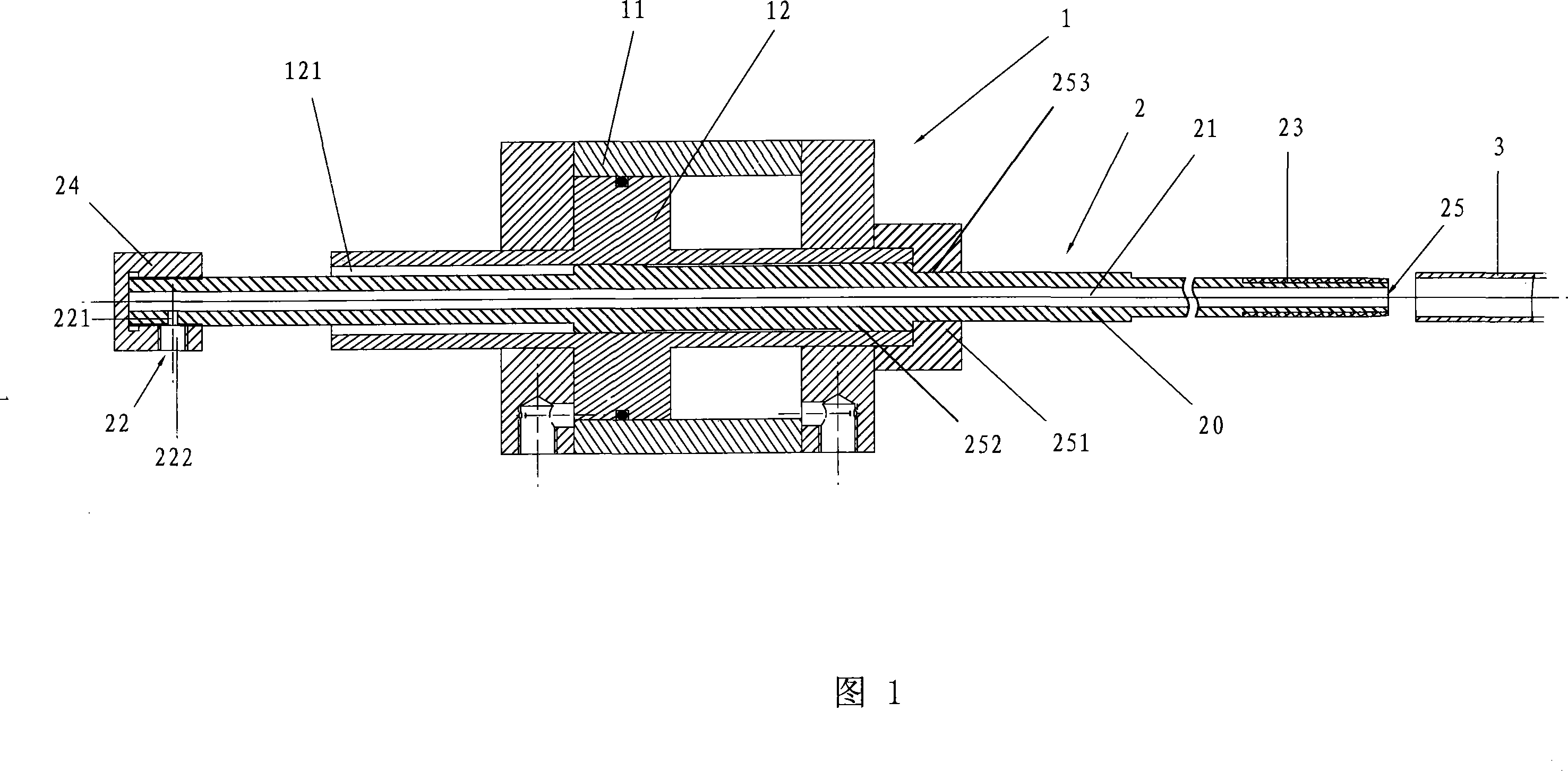
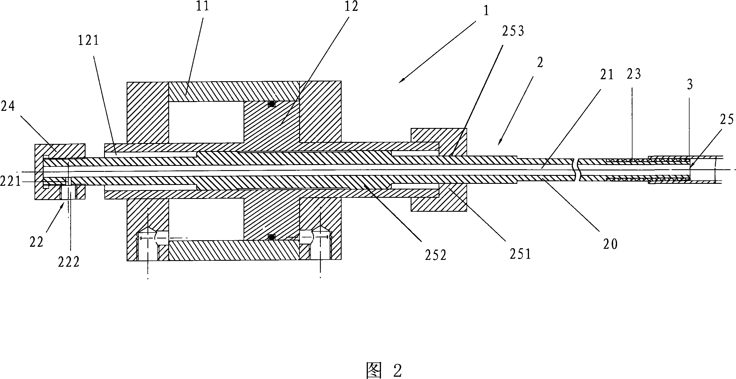
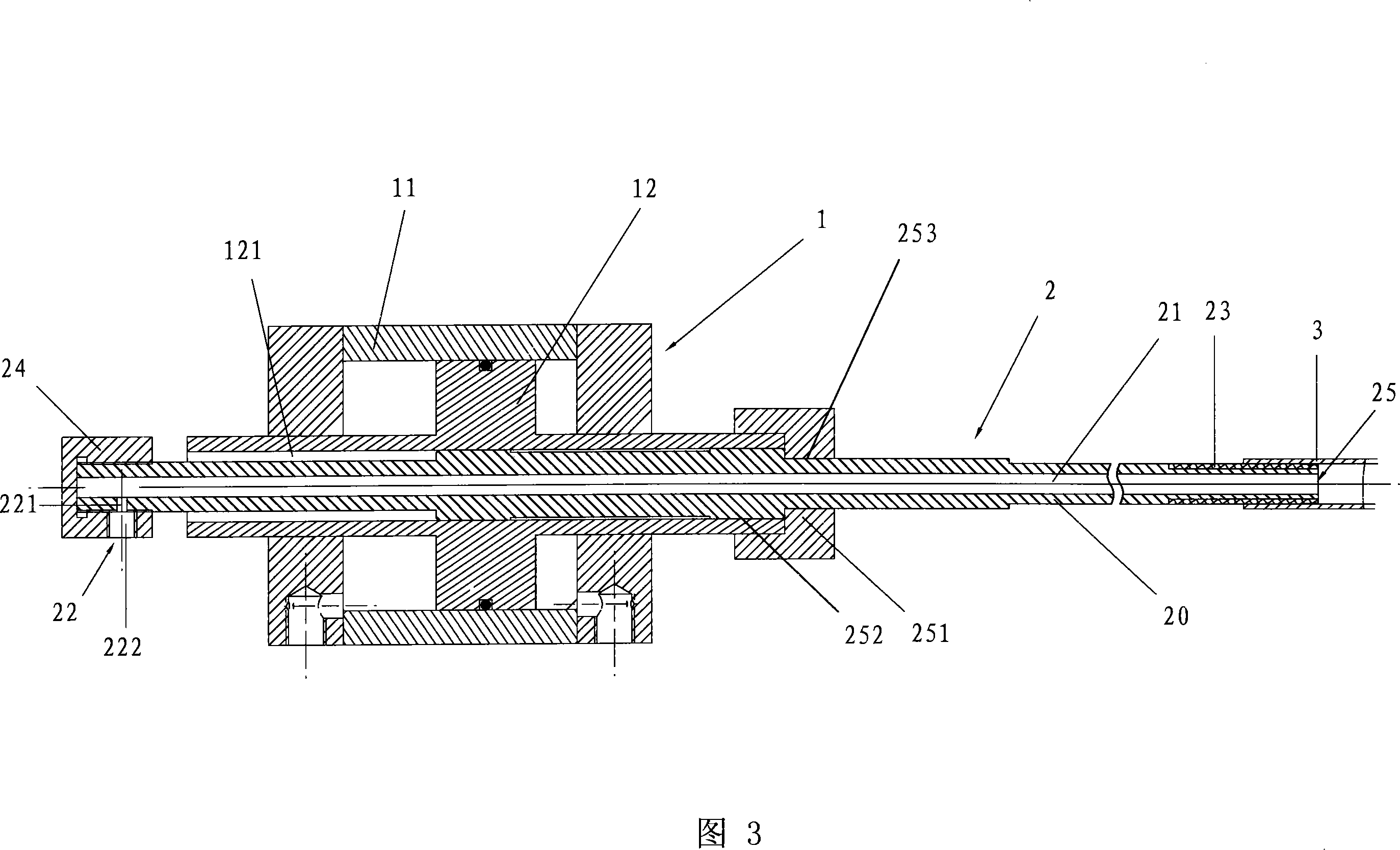
[0016] As shown in FIGS. 1, 2, and 3, the clamping device for forming the spiral energy-saving lamp tube 3 according to the present invention includes a cylinder 1 having a cylinder 11 and a piston rod 12, and a movable rod 2.

[0017] Among them, cylinder 1 is a modified standard thin cylinder. A through hole 121 is opened in the middle of the piston rod 12 along the axial direction, and the movable rod 2 is slidably arranged in the through hole 121.

[0018] The movable rod 2 includes a cylindrical rod body 20 with an air hole 21 along the axial direction. The air hole 21 is an opening 25 at the front end of the rod body 20, and the tail part is also communicated with the outside.

[0019] A ring-shaped rubber sleeve 23 is sleeved on the front end of the movable rod 2. The outer surface of the rubber sleeve is slightly tapered, and the shape of the outer surface is consistent with the inner wa...


PUM


Abstract

The invention relates to a holding device used for formation of a spiral energy-saving lamp tube, which comprises a cylinder provided with a piston rod and a cylinder body and a motion bar, wherein the middle portion of the piston rod is opened with a through-hole along the axis direction, the motion bar is glidingly arranged in the through-hole, the motion bar is opened with a air cavity along the axis direction, and the front end portion of the motion bar is tubular shape, the rear end portion of the motion bar is provided with an air inlet which is capable of being open and closed and connects the air cavity and the outer portion, the front end portion is sealed and connected with a dismountable spiral energy-saving lamp tube, the air cavity is only capable of being communicated with the outer portion via the open position and the air inlet, a spacing device is arranged between the front end portion of the piston rod and the motion bar, the spacing device is capable of leading the motion bar stop sliding when sliding frontward in a certain position relative to the piston bar. The invention has the advantages of simple structure, low production cost, and can be prepared only by transforming the normal thin cylinder. Using the invention is capable of achieving three key steps as clamping of spiral energy-saving lamp tubes in the process of automatic formation, inflation and detachment from clamping.

Description

Technical field [0001] The invention relates to a clamping device for forming a spiral energy-saving lamp tube. Background technique [0002] At present, most of the forming of energy-saving lamps is done manually. When forming, the operator holds the glass tube and heats the glass tube in an open electric furnace. After heating for a period of time, the softened glass tube is placed on a spiral mold to form. While the mold is rotating, hold both ends of the glass tube and move closer to the center of the mold as the glass tube is formed. This manual forming method requires skilled workers to operate to ensure the forming effect, and the consistency of the glass tube formed each time is relatively poor, which affects the pass rate and quality of the glass tube. At the same time, workers continue to work with thousands of degrees of electric heating, and the working conditions are very bad. Therefore, it is necessary to develop a mechanism for automatic tube bending. [0003] In t...

Claims


Application Information

Patent Timeline
IPC IPC(8): C03B23/045H01J9/24
CPCC03B23/045C03B23/06
Inventor 王建平张正江陈建华王锦方
Owner 江苏通力机电集团有限公司
Why Eureka
Try Eureka