Thermal transfer apparatus, system and method

A heat transfer system and heat source technology, applied in the field of heat transfer systems, can solve problems such as system hazards and affecting the performance of cooling system heat transfer systems, and achieve low manufacturing and assembly time and low cost effects

Inactive Publication Date: 2010-10-13
SPECIALIST HEAT EXCHANGERS
View PDF0 Cites 2 Cited by
  • Summary
  • Abstract
  • Description
  • Claims
  • Application Information

AI Technical Summary

Problems solved by technology

The result of such leaks can be a serious hazard to the system in various ways, for example, by adversely affecting the efficiency o

Method used


Image

  • Thermal transfer apparatus, system and method
  • Thermal transfer apparatus, system and method
  • Thermal transfer apparatus, system and method

Examples


Embodiment Construction

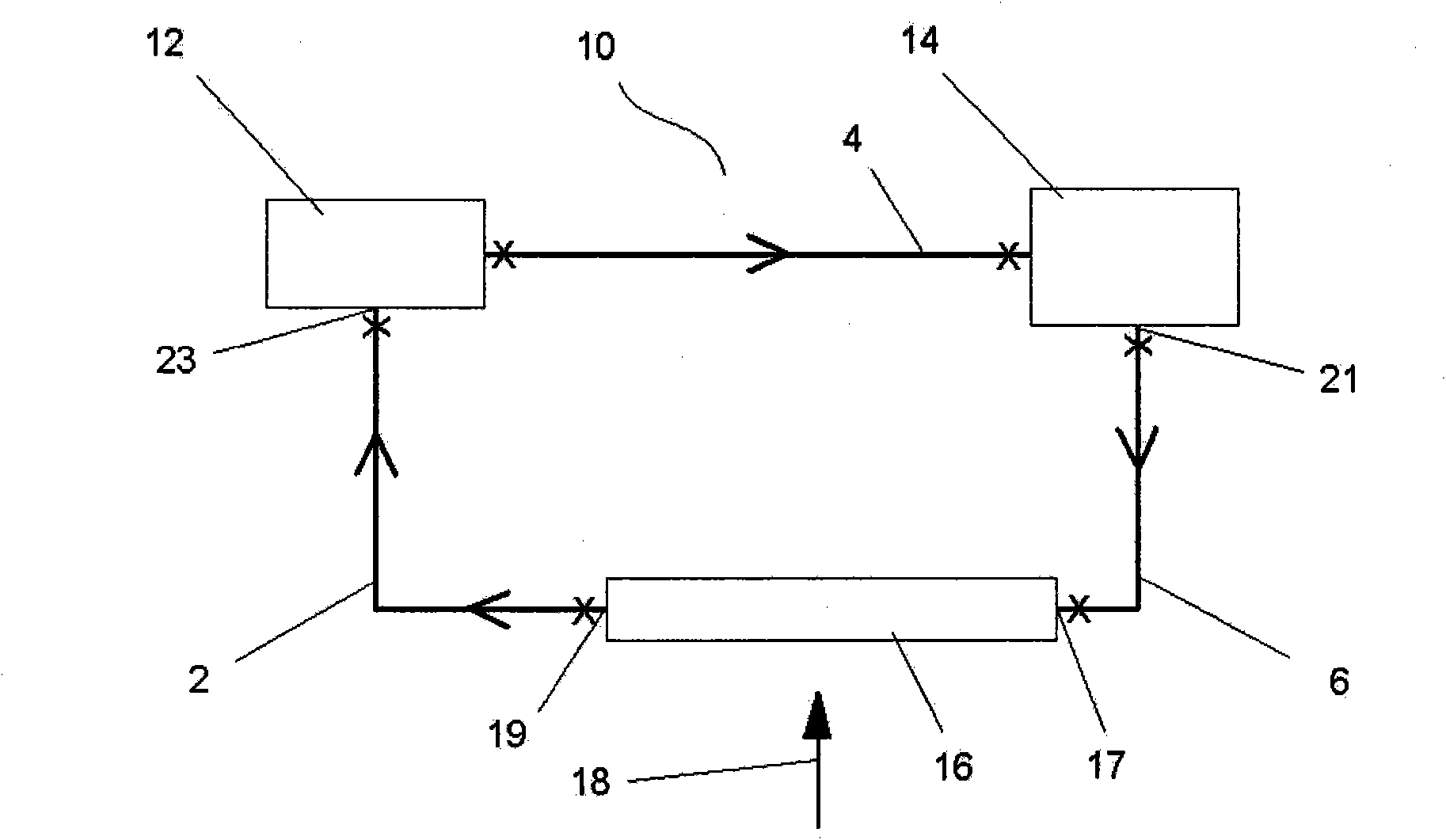
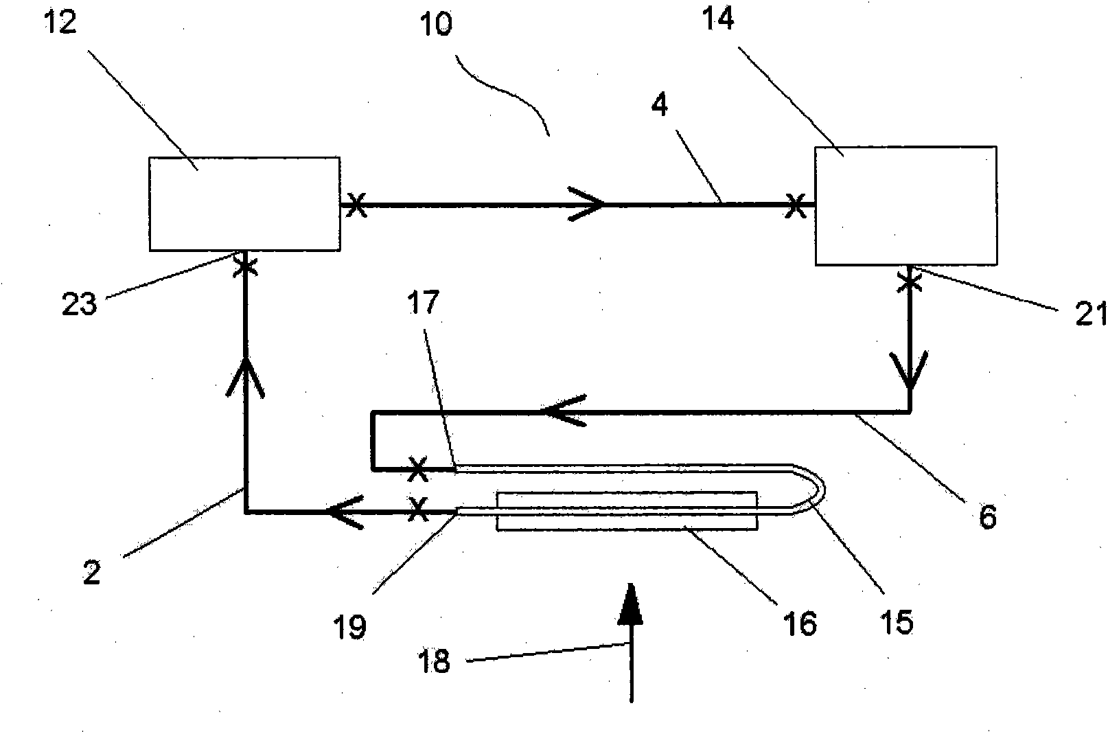
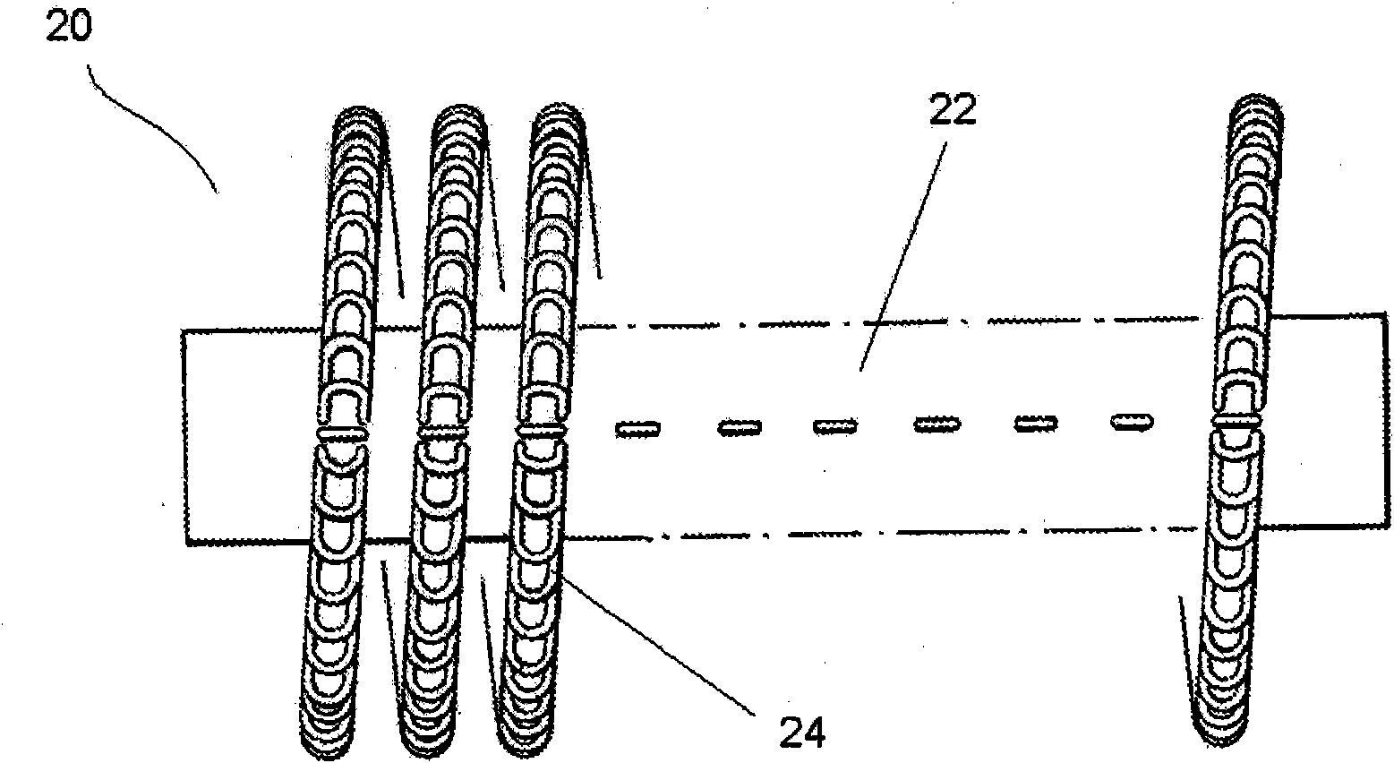
[0080] refer to image 3 , the overall cooling circuit (40, 41, 42) includes fluidly in series: a fluid supply conduit portion (41) having a fluid inlet (54) for connecting to a fluid outlet of a heat source (14); a heat exchange portion ( 40), comprising a heat exchange tube having at least one heat exchange element disposed thereon; and a fluid transfer pipe portion (42), having a fluid outlet (52) for connecting to an inlet of a storage tank (12) to transfer fluid Return to heat source (14). Accordingly, the fluid supply conduit section (41), heat exchange tube and fluid transfer tube section (42) are integrally formed to form a common tube structure (40, 41, 42) manufactured from a single material, eg as a single extrusion.

[0081] An integral cooling circuit (40, 41, 42) may be connected between the heat source (14) and a separate storage tank (12), wherein the fluid inlet (54) of the integral cooling circuit (40, 41 , 42) is connected to the heat source ( 14), and the...


PUM


Abstract

A thermal transfer means comprising, fluidly in series: a fluid supply conduit having a fluid inlet (41) adapted for connection to receive fluid from an outlet of a heat source; a heat exchanger (40) comprising a heat exchanger tube having at least one heat exchanger element disposed thereon; and a fluid delivery conduit (42) having a fluid outlet adapted for connection to deliver fluid to an inlet of a heat source. The fluid supply conduit, heat exchanger tube and fluid delivery conduit are integrally formed from a common tube formation fabricated from a single material. The thermal transfer means is suitable for inclusion into a thermal transfer system, for example on a vehicle, for example to serve as an integral cooling line and/or space heater.

Description

technical field [0001] The present invention relates generally to heat transfer systems, and more particularly, but not limited to, to hydraulic heat transfer systems such as cooling systems. [0002] Thus, the present invention generally relates to systems for transferring thermal energy away from a heat source and / or through a circulating heat supply of a heat transfer fluid (liquid). In particular, the present invention relates to a heat transfer device and a heat transfer tube being a part thereof to enable the transfer of heat from a fluid inside the tube to the environment outside the tube. In particular, the present invention relates to the transfer of heat through a working fluid in an automotive system, such as a power steering (PAS) system, including a heat source such as a power steering pump, or through a dedicated cooling fluid in a cooling system used to cool such an automotive system . The invention also particularly relates to the reduction of leakage in such...

Claims


Application Information

Patent Timeline
IPC IPC(8): F28D7/10F28F9/04
CPCF28F1/36F28D2021/0096F28F2265/16F28F2255/16F28F9/0246B60H1/14F28D7/106
Inventor 保罗·诺索弗
Owner SPECIALIST HEAT EXCHANGERS
Why Eureka
Try Eureka