
Dual-band antenna

a dual-band antenna and antenna technology, applied in the field of antennas, can solve the problem of large size of dipole antennas, and achieve the effect of reducing the volume of antennas

Active Publication Date: 2018-01-02
SERCOMM
View PDF9 Cites 1 Cited by
  • Summary
  • Abstract
  • Description
  • Claims
  • Application Information

AI Technical Summary

Benefits of technology

The invention relates to a dual-band antenna that covers two frequency bands and reduces the size of the antenna. This allows the antenna to be built into communication devices and ensures optimal signal coverage.

Problems solved by technology

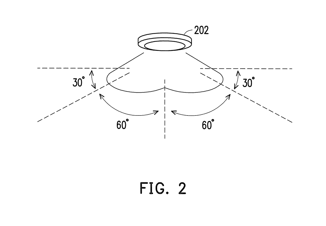
However, since a requirement of today's product design has a trend of small volume and simple shape, the antenna is required to be designed in a way of built-in antenna, and the dipole antenna generally has a too large size, which is not suitable for being disposed in internal of the device.

Method used


Image

  • Dual-band antenna
  • Dual-band antenna
  • Dual-band antenna

Examples


Embodiment Construction

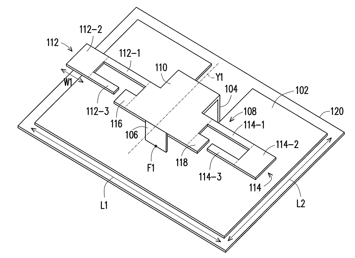
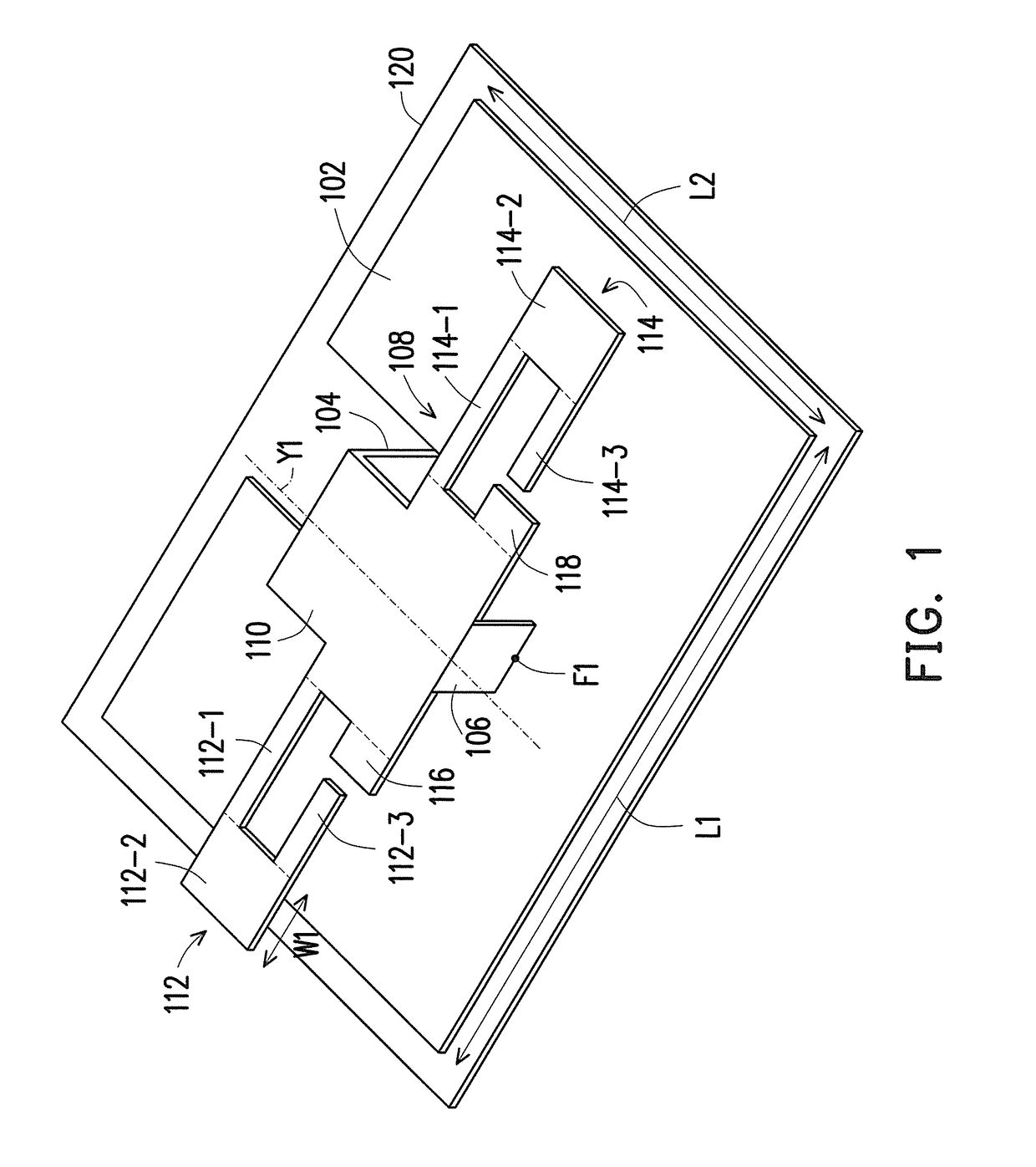
[0013]FIG. 1 is a schematic diagram of a dual-band antenna according to an embodiment of the invention. The dual-band antenna is an inverted-F antenna, which can be applied to a communication device, and the communication device is, for example, wireless access point (AP), though the invention is not limited thereto. The dual-band antenna may include a ground element 102, a short-circuit element 104, a feed element 106 and a radiator 108, where the radiator 108 is parallel to the ground element 102, and the radiator 108 includes a first connection segment 110, a first radiation element 112, a second radiation element 114, a third radiation element 116 and a fourth radiation element 118. A first end of the short-circuit element 104 is connected to the ground element 102, and another end of the short-circuit element 104 is connected to the first connection segment 110. A first end of the feed element 106 has a feed point F1 configured for receiving a feed signal, and a second end of t...


PUM


Abstract

A dual-band antenna including a ground element, a short-circuit element, a feed element and a radiator is provided. The radiator includes a first connection segment, a first radiation element, a second radiation element, a third radiation element and a fourth radiation element. The dual-band antenna covers a first frequency band a second frequency band through the symmetrical first radiation element and second radiation element and the symmetrical third radiation element and fourth radiation element, so as to effectively decrease an antenna volume, and satisfy the requirement of a signal coverage range of a communication device.

Description

CROSS-REFERENCE TO RELATED APPLICATION[0001]This application claims the priority benefit of Chinese application serial no. 201620025806.0, filed on Jan. 12, 2016. The entirety of the above-mentioned patent application is hereby incorporated by reference herein and made a part of this specification.BACKGROUND OF THE INVENTION[0002]Field of the Invention[0003]The invention relates to an antenna, and particularly relates to a dual-band antenna.[0004]Description of Related Art[0005]Regarding a ceiling type communication device, a requirement on an antenna thereof is that a depression angle of a field pattern should be small enough in order to achieve sufficient signal coverage range. Generally, if the antenna is designed in a way of external antenna, a dipole antenna can be adopted to achieve a best coverage range. However, since a requirement of today's product design has a trend of small volume and simple shape, the antenna is required to be designed in a way of built-in antenna, and ...

Claims


Application Information

Patent Timeline
Patent Type & Authority Patents(United States)
IPC IPC(8): H01Q5/00H01Q1/48H01Q9/04H01Q5/30
CPCH01Q5/30H01Q9/0421H01Q1/48H01Q1/007H01Q1/2291H01Q5/371
Inventor KO, CHENG-HUNG
Owner SERCOMM
Learn More