
Method for estimating channel power, method for monitoring frequency spectrum characteristic, apparatus and system

a frequency spectrum characteristic and power estimation technology, applied in the field of multicarrier optical fiber communication technologies, can solve the problems of large system monitoring error amount and inconsistent power of subcarriers, and achieve the effect of quantitatively evaluating the influence of power imbalance

Active Publication Date: 2018-01-02
FUJITSU LTD
View PDF3 Cites 24 Cited by
  • Summary
  • Abstract
  • Description
  • Claims
  • Application Information

AI Technical Summary

Benefits of technology

The patent presents methods to estimate the power of optical channels without adding too much complexity to the system. This helps to monitor and analyze the frequency spectrum of the optical signal.

Problems solved by technology

However, in a practical system, on the one hand, as wavelength and power of a laser are influenced by variation of driving currents, temperature fluctuation, and resonant cavity aging, etc., output carrier wavelength and power will drift in a certain range; and on the other hand, when multicarrier signals pass through the transmission system, the gains of the subcarrier channels are not completely identical, which results in power of the subcarriers are inconsistent.
Such indefinite variation of power brings about relatively large influence to the multicarrier optical communication system, which is mainly embodied in: 1) as the power of the neighboring channels are over large, neighboring channel crosstalk occurs in the central channel in demodulation; and 2) power imbalance results in relatively large errors in system monitoring amount, such as subcarrier interval monitoring amount, and optical signal to noise ratio monitoring amount, etc.

Method used


Image

  • Method for estimating channel power, method for monitoring frequency spectrum characteristic, apparatus and system
  • Method for estimating channel power, method for monitoring frequency spectrum characteristic, apparatus and system
  • Method for estimating channel power, method for monitoring frequency spectrum characteristic, apparatus and system

Examples


embodiment 1

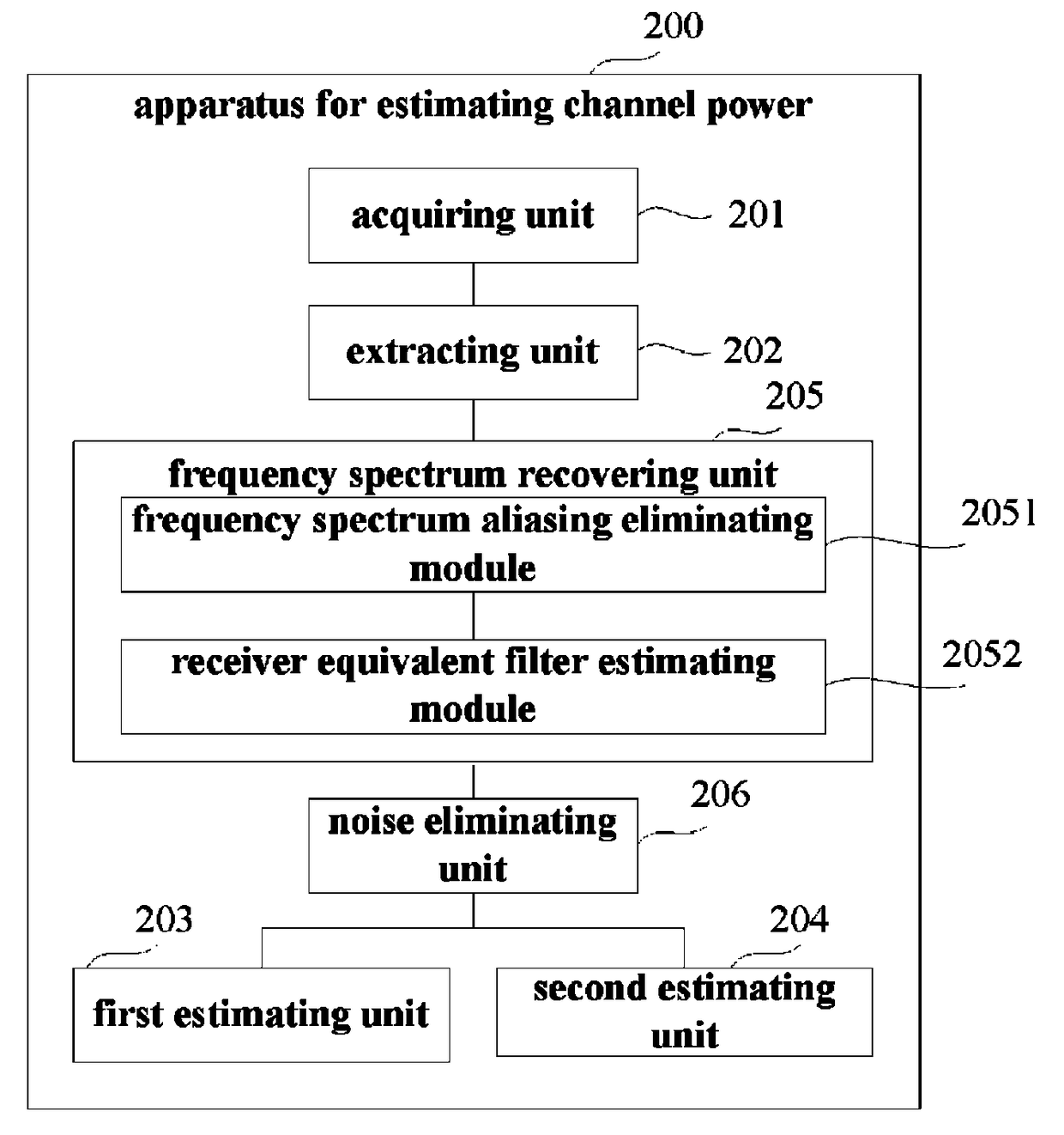
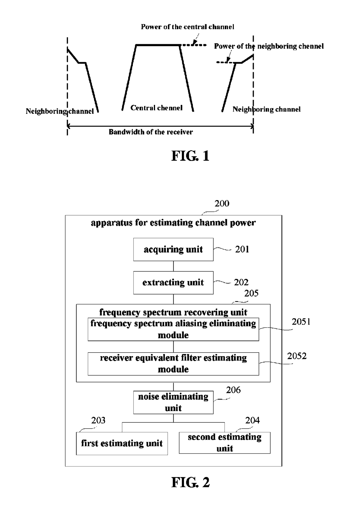
[0043]An embodiment of the present disclosure provides an apparatus for estimating channel power, applicable to a multicarrier optical receiver. FIG. 2 is a schematic diagram of a structure of the apparatus. Referring to FIG. 2, the apparatus 200 includes: an acquiring unit 201, an extracting unit 202, a first estimating unit 203 and a second estimating unit 204. In this embodiment, the acquiring unit 201 is configured to acquire a received signal, the extracting unit 202 is configured to extract frequency spectrum information from the received signal to obtain a frequency spectrum of the received signal, the first estimating unit 203 is configured to estimate power of a central channel in the frequency spectrum according to a power value of a flat area of the central channel, and the second estimating unit 204 is configured to estimate power of a neighboring channel in the frequency spectrum according to a power value of a flat area of the neighboring channel.

[0044]In this embodime...

embodiment 2

[0087]An embodiment of the present disclosure further provides a method for estimating channel power, applicable to a multicarrier optical receiver. As principles of the method for solving problems are similar to that of the apparatus of Embodiment 1, the implementation of the apparatus of Embodiment 1 may be referred to for implementation of the method, and identical contents shall not be described herein any further.

[0088]FIG. 12 is a flowchart of the method for estimating channel power of this embodiment. Referring to FIG. 12, the method includes:

[0089]step 1201: a received signal is acquired;

[0090]step 1202: frequency spectrum information is extracted from the received signal to obtain a frequency spectrum of the received signal;

[0091]step 1203: power of a central channel in the frequency spectrum is estimated according to a power value of a flat area of the central channel; and

[0092]step 1204: power of a neighboring channel in the frequency spectrum is estimated according to a ...

embodiment 3

[0111]An embodiment of the present disclosure further provides a multicarrier optical receiver, including the apparatus for estimating channel power described in Embodiment 1.

[0112]FIG. 15 is a schematic diagram of a structure of the optical receiver of this embodiment. As shown in FIG. 15, the optical receiver 1500 may include a central processing unit (CPU) 1501 and a memory 1502, the memory 1502 being coupled to the central processing unit 1501. It should be noted that this figure is illustrative only, and other types of structures may also be used, so as to supplement or replace this structure and achieve telecommunications function or other functions.

[0113]In an implementation, the functions of the apparatus for estimating channel power described in Embodiment 1 may be integrated into the central processing unit 1501.

[0114]In another implementation, the apparatus for estimating channel power and the central processing unit 1501 may be configured separately. For example, the app...


PUM


Abstract

A method, apparatus and system estimating channel power, and monitoring a frequency spectrum characteristic. A method for estimating channel power includes extracting frequency spectrum information from a received signal, so as to obtain a frequency spectrum of the received signal, estimating power of a central channel in the frequency spectra according to a power value of a flat area of the central channel, and estimating power of a neighboring channel in the frequency spectra according to a power value of a flat area of the neighboring channel. With the embodiments of the present disclosure, the power of the central channel and the power of the neighboring channel may be estimated by using only frequency spectrum information obtained by a single optical receiver, so as to quantitatively evaluate influence of a power imbalance effect, thereby ensuring precision of the power estimation, and reducing effects of nonideal factors on the estimated values.

Description

CROSS-REFERENCE TO RELATED APPLICATION[0001]This application claims the priority benefit of Chinese Patent Application No. 201510177838.2, filed on Apr. 15, 2015 in the Chinese State Intellectual Property Office, the disclosure of which is incorporated herein in its entirety by reference.BACKGROUND[0002]1. Field[0003]The present disclosure relates to the field of multicarrier optical fiber communication technologies, and in particular to a method for estimating channel power, a method for monitoring a frequency spectrum characteristic, an apparatus and a system.[0004]2. Description of the Related Art[0005]In a multicarrier optical fiber communication system, subcarrier data are modulated in several optical carriers independent of each other, and a receiver receives and demodulates the subcarrier data respectively. Under an ideal condition, power of each subcarrier channel is stable, and a central channel received by a single receiver is less affected by neighboring channels. However...

Claims


Application Information

Patent Timeline
Patent Type & Authority Patents(United States)
IPC IPC(8): H04B10/69H04B10/079G01J3/00
CPCH04B10/07955H04B10/07957G01J3/00
Inventor ZHAO, YINGDOU, LIANGTAO, ZHENNING
Owner FUJITSU LTD
Learn More