Eureka AIR delivers breakthrough ideas for toughest innovation challenges, trusted by R&D personnel around the world.

System and method of operating a constant current light-emitting diode pulsing drive circuit

Active Publication Date: 2018-01-09
DATALOGIC USA INC
View PDF4 Cites 2 Cited by
  • Summary
  • Abstract
  • Description
  • Claims
  • Application Information

AI Technical Summary

Benefits of technology

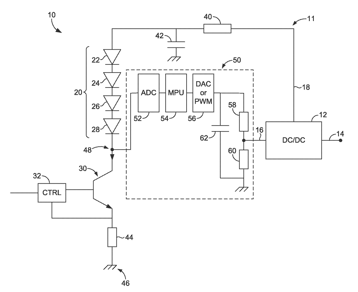
The patent is about improving the operation of a constant current LED pulsing drive circuit that uses narrow constant current pulses. The circuit includes a pulsed constant current source and a series of LEDs. The bias voltage applied to the LEDs is periodically adjusted to compensate for changes in forward voltage caused by temperature variations or other factors. This allows for consistent operation of the LEDs even when the temperature changes. The method includes measuring the intermediate voltage between the LEDs and the constant current source and adjusting the bias voltage to ensure that the intermediate voltage does not exceed the second component of the bias voltage. This helps to maintain the proper bias voltage for optimal operation of the LEDs.

Problems solved by technology

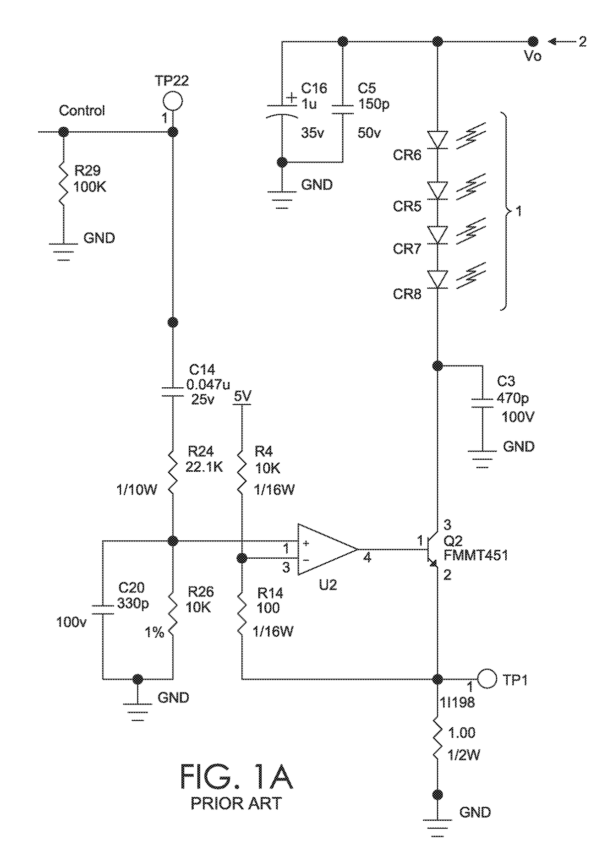
This is inefficient, however, because the Vmin of each of the series of four LEDs 1 may be less than 3.4 volts (in fact, the Vmin could be as small as half that amount).
When a supplied voltage exceeds the Vmin, the additional voltage supplied may be converted into heat, increasing wear and power consumption, and thus require thermal management parts.
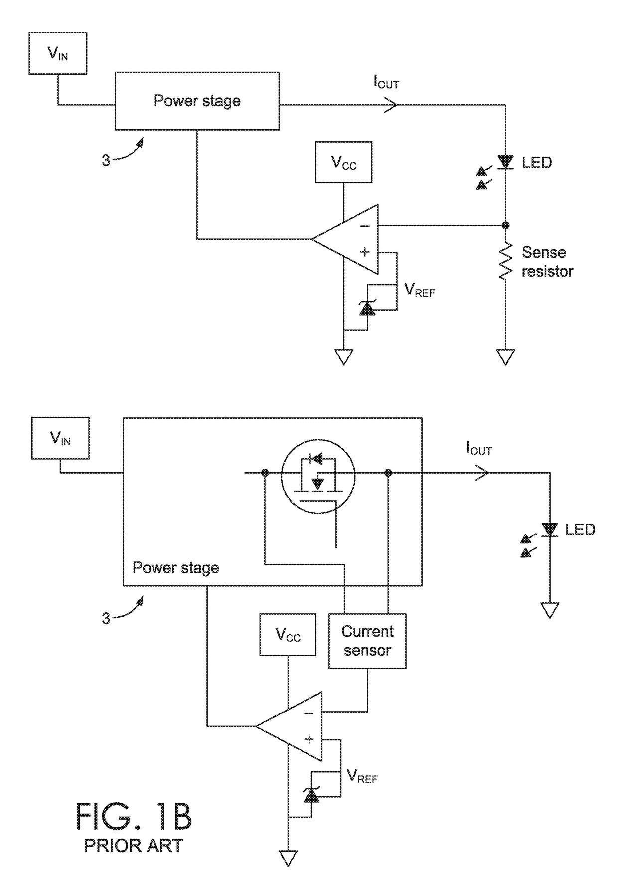
While these previous schemes improve efficiency in some circumstances, the adjustment of the bias voltage to a stable state is limited by the electric circuit response time (i.e., the time it takes from bias voltage adjustment start to output stabilized).
In applications having pulses shorter than the response time of the circuit (e.g., as short as 300 microseconds or less), the previously proposed schemes do not work because the response time is too long.
Attempting to implement the previously proposed schemes in applications with short pulse width (e.g., less than 300 microseconds) causes unexpected changes in voltage and / or instability in the system.

Method used


Image

  • System and method of operating a constant current light-emitting diode pulsing drive circuit
  • System and method of operating a constant current light-emitting diode pulsing drive circuit
  • System and method of operating a constant current light-emitting diode pulsing drive circuit

Examples


Embodiment Construction

[0023]Subject matter is described throughout this disclosure in detail and with specificity in order to meet statutory requirements. But the aspects described throughout this disclosure are intended to be illustrative rather than restrictive, and the description itself is not intended necessarily to limit the scope of the claims. Rather, the claimed subject matter might be practiced in other ways to include different elements or combinations of elements that are equivalent to the ones described in this disclosure. In other words, the intended scope of the invention includes equivalent features, aspects, materials, methods of construction, and other aspects in embodiments not expressly described or depicted in this application in the interests of concision, but which would be understood by an ordinarily skilled artisan in the relevant art in light of the full disclosure provided herein as being included within the inventive scope. It will be understood that certain features and subco...


PUM


Abstract

Tuning a bias voltage supplied to a series of one or more LEDs in a constant current LED pulsing drive circuit may comprise the steps of: (A) setting the bias voltage to a test value, the test value being at least equal to the sum of the bias voltage second component and the maximum forward voltage rating of each of the one or more LEDs; (B) measuring an intermediate voltage present between the series of one or more LEDs and the constant current source when the LEDs are turned on; (C) determining if the intermediate voltage exceeds the second component of the bias voltage; and (D) upon determining the intermediate voltage exceeds the second component of the bias voltage, reducing the bias voltage applied to the one or more LEDs by an amount necessary to cause the intermediate voltage to equal the second component of the bias voltage.

Description

CROSS-REFERENCE TO RELATED APPLICATIONS[0001]Not applicable.TECHNICAL FIELD[0002]This disclosure describes systems of, and methods to efficiently operate, constant current light-emitting diode (“LED”) pulsing drive circuits where the pulses of current have very short duration.BACKGROUND OF THE INVENTION[0003]A “forward voltage” as used herein refers to the voltage drop across a component, or a plurality of components, of a constant current LED pulsing drive circuit. For example, the forward voltage across an LED is the voltage drop across the LED. Similarly, the forward voltage across a series of LEDs is the voltage drop across the series of LEDs.[0004]A “bias voltage” as used herein refers to a voltage having a value comprised of at least two components: a first component associated with the forward voltage across one or more LEDs, and a second component associated with the voltage across the other components in series with the one or more LEDs.[0005]An LED will emit light when at ...

Claims


Application Information

Patent Timeline
IPC IPC(8): H05B33/08H05B37/02H05B44/00
CPCH05B33/0827H05B37/0281H05B33/0887H05B33/0842H05B45/46H05B45/10
Inventor GAO, WENLIANGO'DONNELL, PAT
Owner DATALOGIC USA INC
Why Eureka
Eureka Blog
Learn More