
Constant current output type induction type wireless power transmission converter and parameter selection method thereof

A technology of wireless power transmission and constant current output, which is applied in the direction of conversion equipment, electrical components, and circuit devices with intermediate conversion to AC, which can solve the problems of reducing system efficiency and reliability, system instability, bifurcation, etc.

Active Publication Date: 2014-10-08
SOUTHEAST UNIV
View PDF2 Cites 52 Cited by
  • Summary
  • Abstract
  • Description
  • Claims
  • Application Information

AI Technical Summary

Problems solved by technology

The above characteristics make it difficult for the inductive wireless power transfer converter to directly output the current required by the load within a certain range of input voltage and load. Additional cost and control will reduce system efficiency and reliability; the second is to use frequency conversion control, but frequency conversion control will cause bifurcation, resulting in system instability
In addition, frequency conversion control is difficult to optimize the design of magnetic components

Method used


Image

  • Constant current output type induction type wireless power transmission converter and parameter selection method thereof
  • Constant current output type induction type wireless power transmission converter and parameter selection method thereof
  • Constant current output type induction type wireless power transmission converter and parameter selection method thereof

Examples


Embodiment Construction

[0063] The present invention will be further described in detail below in conjunction with the accompanying drawings and LED lighting application examples.

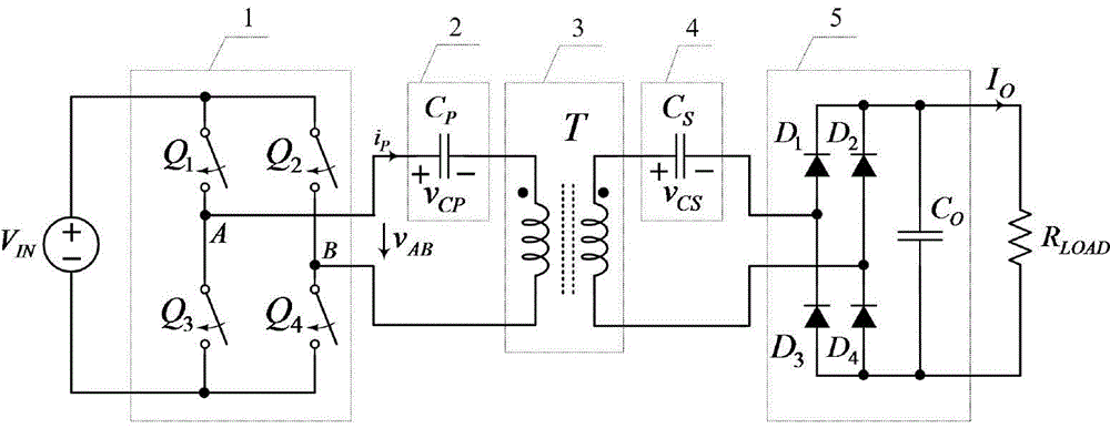
[0064] The constant current output type inductive wireless power transmission converter involved in the present invention is as attached figure 1 As shown, it includes a high-frequency inverter circuit 1, a primary side compensation capacitor 2, a loosely coupled transformer 3, a secondary side compensation capacitor 4, a rectification filter circuit 5 and a load. The high-frequency inverter circuit consists of a switching tube Q 1 , Q 2 , Q 3 , Q 4 Composed, the rectification and filtering circuit is composed of diode D 1 、D 2 、D 3 、D 4 and the output filter capacitor C O composition. High-frequency inverter circuit 1 input DC input source V IN , the positive pole of the primary side compensation capacitor 2 is connected to the middle point A of the bridge arm of the high frequency inverter circuit 1, the negat...


PUM


Abstract

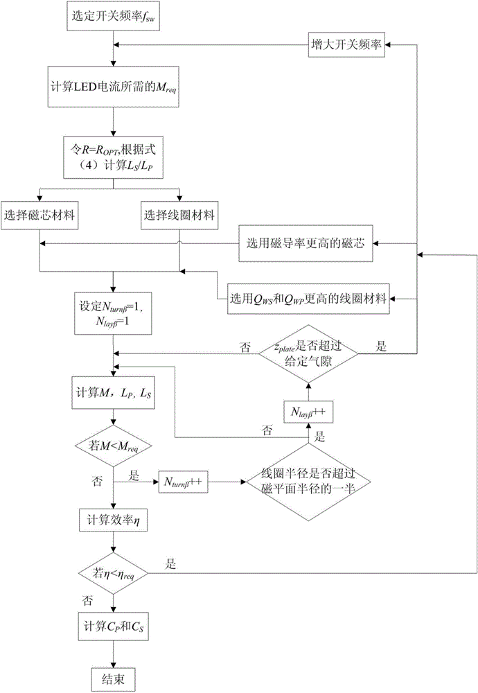
The invention relates to a constant current output type induction type wireless power transmission converter and a parameter selection method of the constant current output type induction type wireless power transmission converter. The constant current output type induction type wireless power transmission converter and the parameter selection method are suitable for induction type wireless power transmission occasions with fixed air gaps and current type loads. The converter comprises a high-frequency inverter circuit, a primary side compensation capacitor, a loose coupling transformer, an auxiliary side compensation capacitor, a rectification filtering circuit and a load. The resonant frequency of the primary side compensation circuit is equal to that of the auxiliary side compensation circuit, the high-frequency inverter circuit works at the resonant frequency, converter output currents are from a constant current source, the magnitude of the output currents is only relevant to input voltages and the mutual inductance of the loose coupling transformer, input impedance is pure, reactive circulation and device stress are reduced, and efficiency is improved. Converter constant current output characteristics are taken into consideration in the parameter selection method, and on the premise that the distance between the air holes, the size of the transformer and the load are given, mutual inductance, inductance values and coupling coefficients of primary side windings and auxiliary side windings are acquired iteratively with efficiency maximization of the converter as the goal.

Description

technical field [0001] The invention relates to a constant current output type inductive wireless power transmission converter and a parameter selection method thereof, which are suitable for inductive wireless power transmission occasions with fixed air gaps and current loads, such as electric vehicle charging and LED lighting. Background technique [0002] Inductive wireless power transmission is based on the principle of electromagnetic induction, using electromagnetic fields as the medium to transfer energy from the input source to the load without direct electrical and mechanical contact. This technology has the advantages of safety, convenience, high reliability, and high efficiency, and has great application potential in the fields of electric vehicle charging, biomedicine, and LED lighting. [0003] The output characteristics of inductive wireless power transmission converters are relatively complex, which are related to transformer parameters, compensation network s...

Claims


Application Information

Patent Timeline
IPC IPC(8): H02J17/00H02M3/28H02J50/12
Inventor 曲小慧韩洪豆黄少聪
Owner SOUTHEAST UNIV
Learn More