Detection signal processing circuit and detection signal processing apparatus for a rotation sensor

a detection signal and processing circuit technology, applied in the direction of speed/acceleration/shock measurement, measurement devices, instruments, etc., can solve the problems of increasing the electric power consumption of the rotation sensor, the weight of the wiring, and the wiring space. to achieve the effect of reducing the electric potential and reducing the electric power consumption

Inactive Publication Date: 2008-03-18
DENSO CORP
View PDF5 Cites 52 Cited by
  • Summary
  • Abstract
  • Description
  • Claims
  • Application Information

AI Technical Summary

Benefits of technology

[0009]In view of the above-described problems, the present invention has an object to provide a detection signal processing circuit for a rotation sensor and a related apparatus capable of outputting detection signals representing the rotational direction and the rotational speed of a rotor with three wiring cables and also capable of reducing electric power consumption.

Problems solved by technology

Using a total of four cables for each rotation sensor will cause the problems of wiring weight and wiring space.
Accordingly, electric power consumption of the rotation sensor will increase.
As described above, when the rotation sensor is positioned far from the ECU to detect the rotation of a wheel, the electric power consumption in the wiring will also increase.
This is the reason why the above-described conventional technique is not preferably applicable to heavy-duty trucks or buses due to their longer bodies.

Method used


Image

  • Detection signal processing circuit and detection signal processing apparatus for a rotation sensor
  • Detection signal processing circuit and detection signal processing apparatus for a rotation sensor
  • Detection signal processing circuit and detection signal processing apparatus for a rotation sensor

Examples


first embodiment

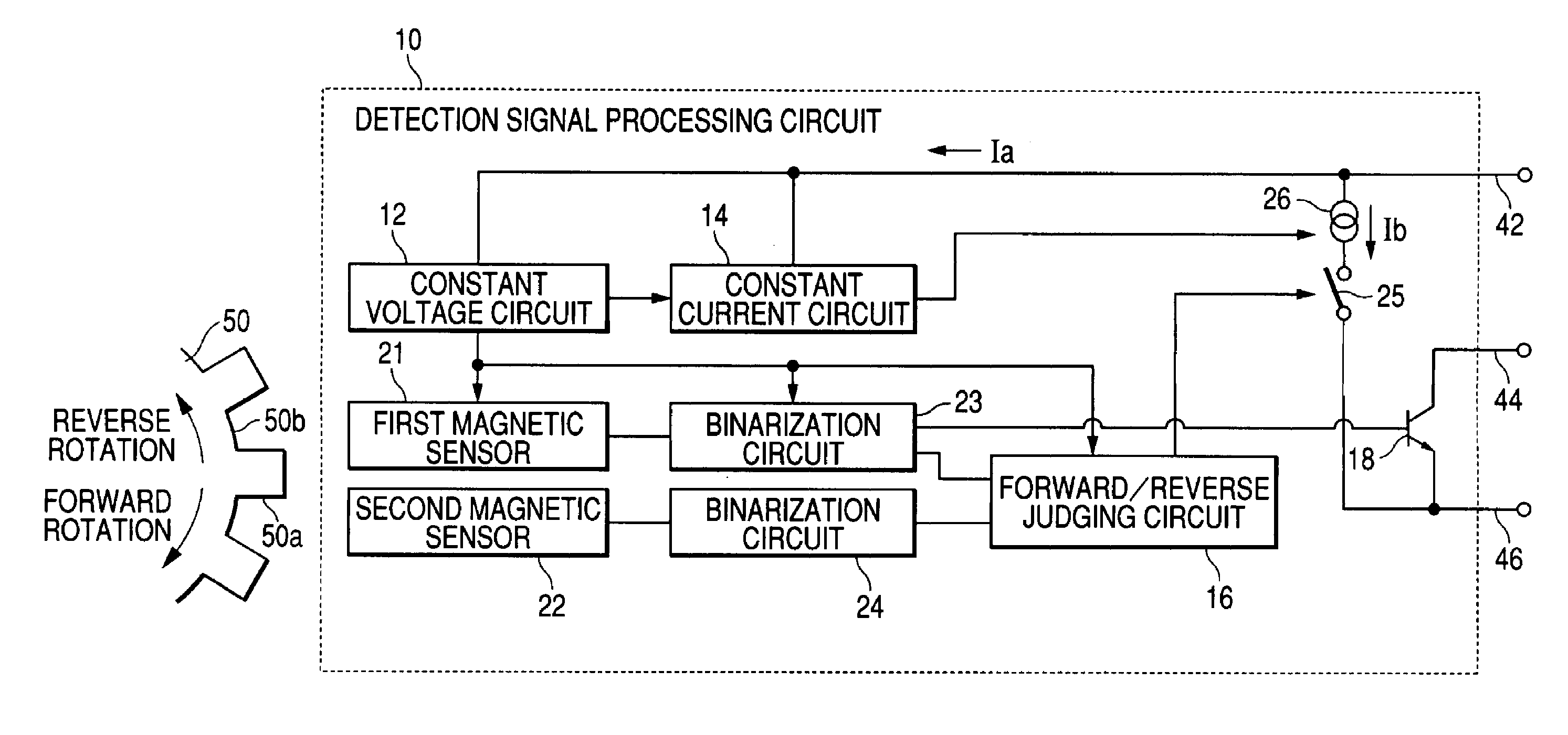
[0040]Hereinafter, a rotation sensor capable of detecting both the rotational speed and the rotational direction of a wheel of an automotive vehicle will be explained in accordance with a first embodiment of the present invention with reference to FIGS. 1 to 6. The rotation sensor is, for example, disposed at an appropriate portion (i.e. rotation detecting portion) near a wheel of an automotive vehicle to detect a rotational condition of this wheel. The rotation sensor is associated with an ABS (i.e. Antilock Brake System), a VSC (Vehicle Stability Control) or other control device installed in the automotive vehicle. The rotation sensor must accurately detect the rotational speed of the wheel in both forward and backward directions in a wide range covering lower speeds and higher speeds.

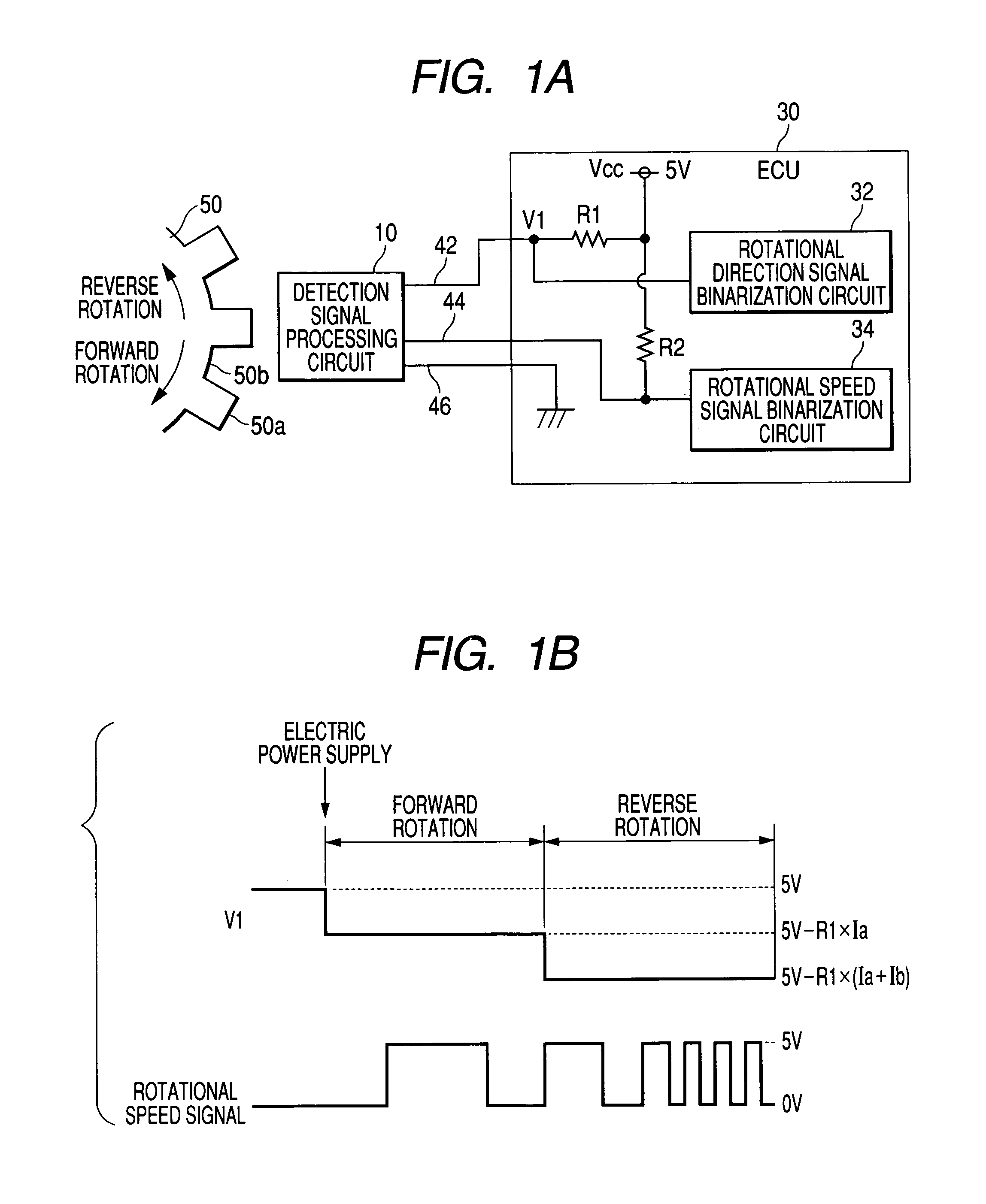
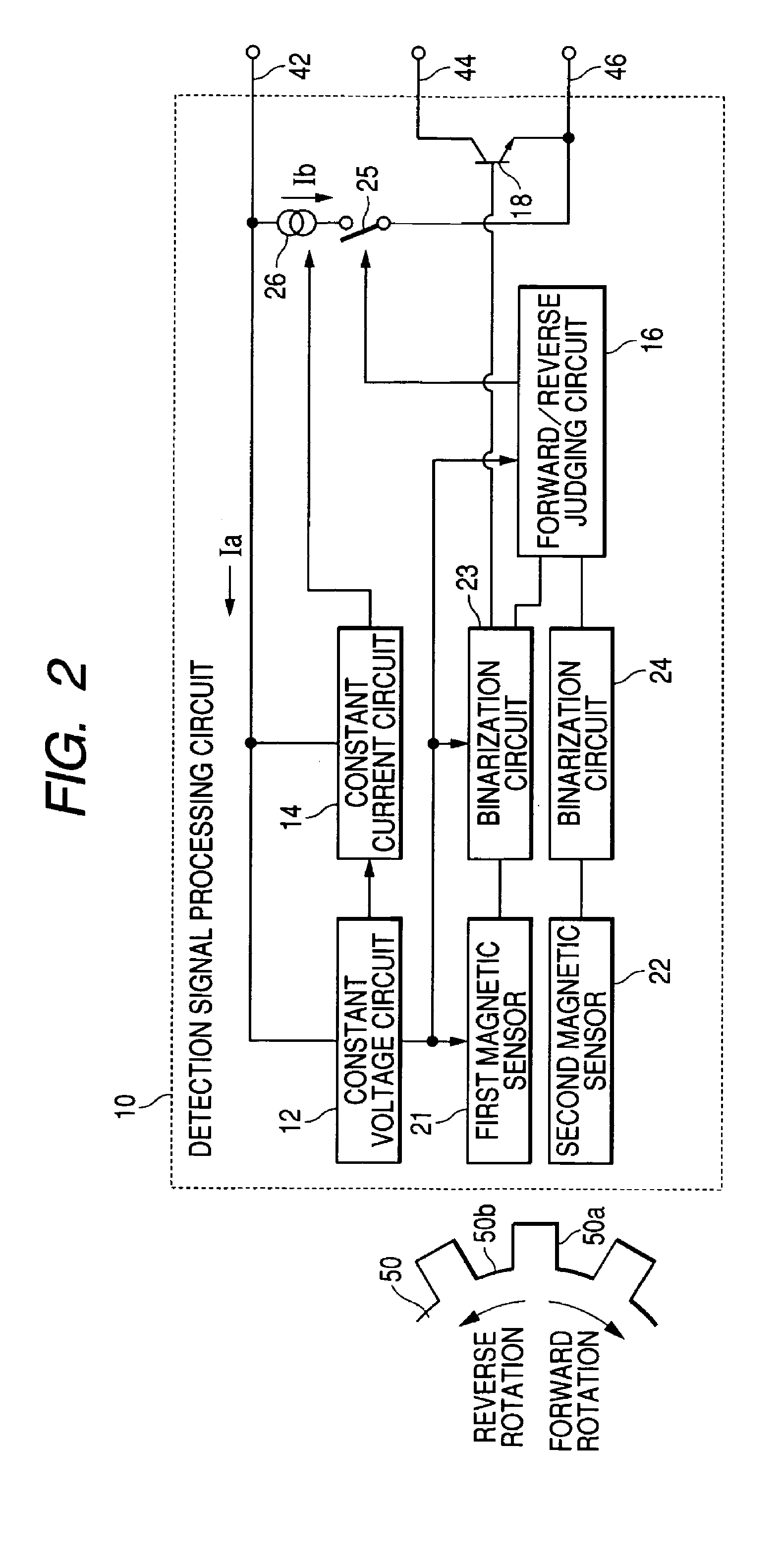
[0041]FIG. 1A is a block diagram showing a detection signal processing circuit and ECU (i.e. electronic control unit) in accordance with a first embodiment of the present invention. A brake control E...

second embodiment

[0056]Hereinafter, a detection signal processing circuit for a rotor and a related detection signal processing apparatus in accordance with a second embodiment of the present invention will be explained with reference to FIGS. 7 and 8. FIG. 7 is a block diagram showing a detection signal processing circuit and ECU in accordance with the second embodiment of the present invention. FIG. 8 is a block diagram showing a detailed arrangement of the detection signal processing circuit shown in FIG. 7. According to the above-described first embodiment explained with reference to FIGS. 1A and 2, the electric potential detecting resistor R1 and the pull-up resistor R2 are provided in the ECU 30. The second embodiment is differentiated in that both of an electric potential detecting resistor R1′ and a pull-down resistor R2′ are provided in the detection signal processing circuit 10.

[0057]According to the detection signal processing apparatus for a rotation sensor of the second embodiment of th...


PUM


Abstract

Detecting the rotational direction of a rotor is feasible by allowing a constant current source to supply a constant current flowing from an electric potential supply line to the earth in response to a turning-on action of a switch. Accordingly, detecting both the rotational speed and the rotational direction of the rotor is feasible by using three wiring cables of a power source line, an earth line, and a signal line outputting a pulse signal in accordance with the rotation of the gear. Using such a one-stage voltage adjustment enables the detection signal processing circuit to reduce electric power consumption compared with a system requiring a two-stage voltage adjustment.

Description

CROSS-REFERENCE TO RELATED APPLICATION[0001]This application is based upon and claims the benefit of priority from earlier Japanese Patent Application No. 2004-57908 filed on Mar. 2, 2004 so that the description of which is incorporated herein by reference.BACKGROUND OF THE INVENTION[0002]The present invention relates to a detection signal processing circuit for a rotation sensor and a related apparatus capable of detecting the rotational direction and the rotational speed of a rotor based on detection signals of two sensing elements.[0003]The rotation sensors, capable of accurately detecting not only a rotational angle but also a rotational direction (e.g. reverse rotation such as backlash), are preferably used as crank angle sensors and cam angle sensors for automotive vehicles. FIG. 9A is a detection signal processing circuit 110 applicable to this kind of rotation sensor. The detection signal processing circuit 110 includes two magnetic sensors (not shown) disposed in a confront...

Claims


Application Information

Patent Timeline
Patent Type & Authority Patents(United States)
IPC IPC(8): G01P13/00G01B7/30G01P3/54G01P3/489G01P3/481G01P3/52G01P13/04
CPCG01P13/045
Inventor OKADA, HIROSHISUGIKI, MIKIOMAKINO, YASUAKI
Owner DENSO CORP
Why Eureka
Try Eureka