Apparatus and method to enhance the life of Light Emitting diode (LED) devices in an LED matrix

a technology of led matrix and led light, applied in the direction of electric variable regulation, process and machine control, instruments, etc., can solve the problems of inability to meet the requirements of road lamps, require more complex source drivers and sensors, and scarify the light intensity, so as to avoid over stress of leds, small space to implement, adapt flexible

Inactive Publication Date: 2010-11-04
PONG MAN HAY +1
View PDF8 Cites 55 Cited by
  • Summary
  • Abstract
  • Description
  • Claims
  • Application Information

AI Technical Summary

Benefits of technology

[0013]The present invention can significantly enhance the life of LED chips and LED lamps that operates at high temperature. The invention comprises of a set of controllable spare LEDs to share the current of the main LED matrix drive by a constant current source and reduce the main LEDs' junction temperature. Converter circuit, controller and sensor is included to enable the spare LED to work in the desired operating region
[0014]The invention comprises of a set of spare LEDs chip powered by a converter in parallel to an LED matrix. It further comprises of a controller that receives feedback from the temperature sensors on the thermal pad of the lamp. The controller calculates the expected life. The controller can be implemented by an MCU, FPGA, analogue IC or other integrated circuit means. While the temperature rises and the expected life of the LED matrix may fall below the specified time span, the controller turns on the spare LED matrix. Current is then branched to the converter and current flows through the main LED matrix will be reduced. The junction temperature will also reduce instantly and the life can be lengthened. The reason to implement a buck converter is to provide accurate control of the power delivery to the spare LED. The operation point of the main LED matrix can be tuned for long life while the spare LED compensate for the drop in brightness of the main LED matrix and preserve overall illumination. The converter also prevents the spare LEDs from over voltage, due to the imperfect transient response of the LED drivers. During the voltage changes from the main LED matrix to the spare LED matrix to fit the constant current, the instantaneous high voltage from the current source would deteriorate the spare LEDs.
[0015]The invention can greatly enhance life the LED, especially those operated outside the designed operating temperature. For example, in a case where 6 typical LED chips with 13 K / W thermal pad is packed together with a 30 K / W heatsink and a 2 LED chips serial is paralleled as the spare ones, the life can be enhanced from 10000 hr to 60000 hr.
[0017]Unlike the solution by using bigger heatsink, the apparatus of the present invention requires a small space to implement. It fits right into the lamp compartment. Since the apparatus of the present invention is intelligent with a processor, it can be adapted flexibly to avoid over stressing the LEDs even in extreme cases. It can be implemented with common LED chips. It has no mechanical moving part which impairs reliability. The invention can instantly adapt with the state of the art high temperature high power LEDs or common lighting class LEDs, so the LEDs can work fine in their own territories continuously, with enhanced life time and extra protection.
[0018]Brightness can be maintained and controlled so it does not suffer from light reduction, compare to the traditional switching off scheme. Plus the feature that it does not require replacing the mature constant current driver with a tailor made variable current source.

Problems solved by technology

This method scarifies the light intensity and more complex driver is required.
It requires more complex source driver and sensors have to link to the driver.
It is not practicable in some cases of road lamps.
The second method is increasing the power supplied to the LED to maintain the luminous flux, but it would further shorten the life of the LED.
The increased current leads to increasing power and further heat up the LED.
Also, no two semiconductor devices are identical.
Therefore it is not easy to transmit the temperature information at the lamp and other data to the driver far away.

Method used


Image

  • Apparatus and method to enhance the life of Light Emitting diode (LED) devices in an LED matrix
  • Apparatus and method to enhance the life of Light Emitting diode (LED) devices in an LED matrix
  • Apparatus and method to enhance the life of Light Emitting diode (LED) devices in an LED matrix

Examples


Embodiment Construction

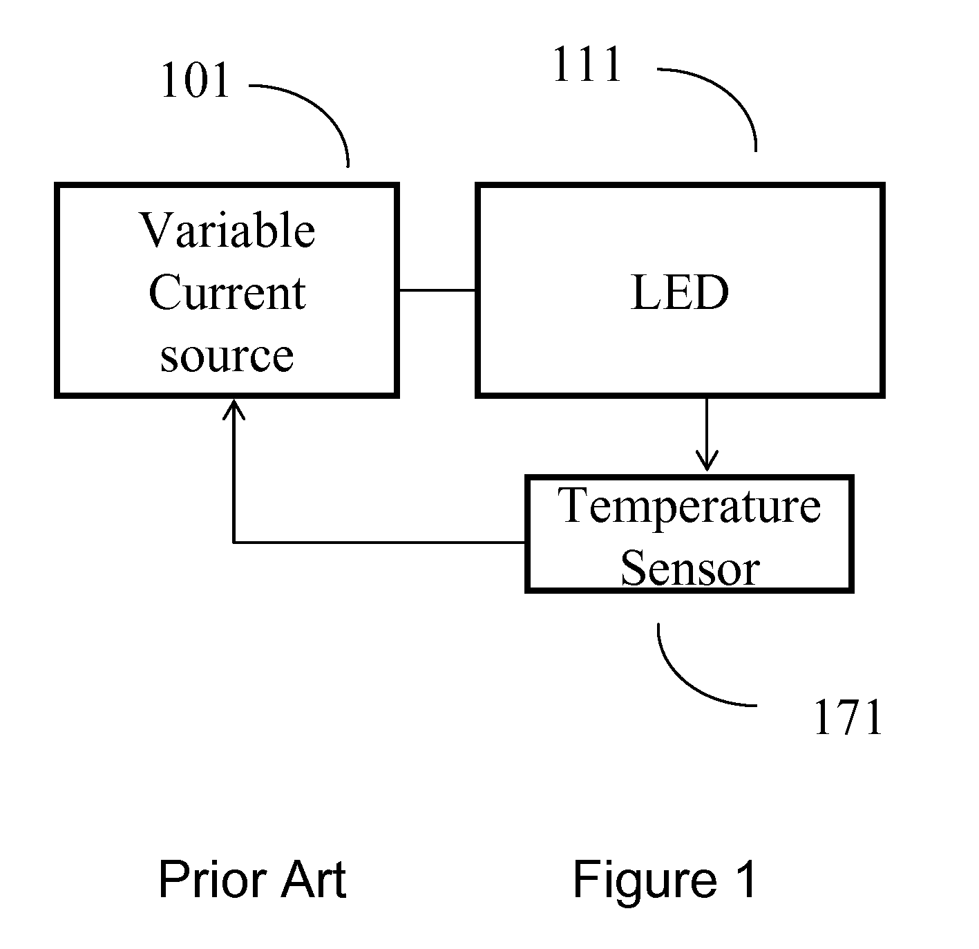
[0028]The prior art setup of temperature compensated LED apparatus is illustrated in FIG. 1. LED 111 is powered by a variable current source 101. Temperature sensor 171 senses the temperature of the LED and feedback a signal to the current source 101. The current source adjusts the supply current to the LED. Many researchers teach how to build the feedback circuit, the hardware design of the sensing equipment and the controlling algorithm. These solutions have a common point. The sensor 171 must be placed near to LED 111 to sense correctly, and the feedback signal from the sensor must be connected to the current source 101. There are two limitations. First the feedback line must be long if the LED 111 is placed far from the current source 101, or the current source 101 would be heated up by LED 171 if there are placed close to each other. Second a variable current source is more complex than a constant current source.

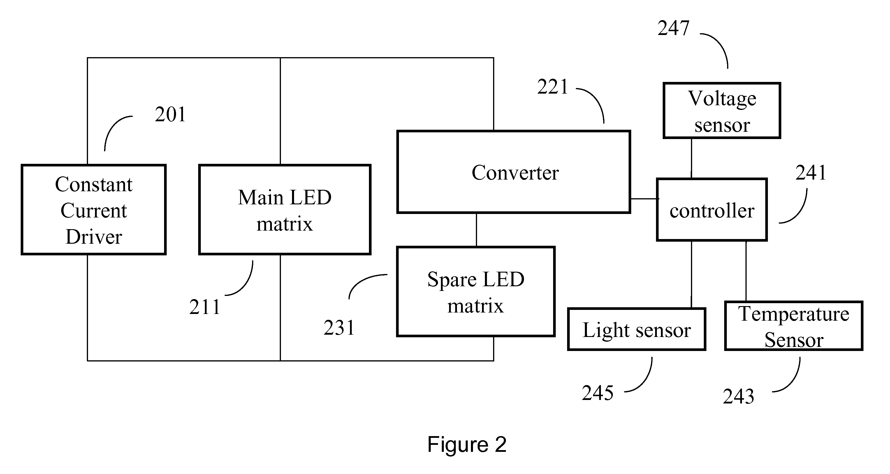
[0029]A basic embodiment of the present invention comprises of fou...


PUM


Abstract

The present invention is an apparatus to enhance the Life of LED devices in an LED matrix for illumination. It comprises of a spare LED matrix in addition to a main LED matrix. It further comprises of a constant current source which is the power source. Such constant current source is coupled directly to said main LED matrix and powers it up accordingly. In adverse conditions, say when the ambient temperature is high, continuous operation of said main LED matrix at full power will deteriorate the LED life. A power converter coupled to said constant current source operates and draws current to power on said spare LED matrix. This relieves said main LED matrix from full power and the reduction in illumination is largely compensated by said spare LED matrix. This invention further comprises a controller which senses temperature and other parameters and operates said spare LED matrix intelligently. The present invention is also a method to operate said apparatus to maximize LED life or to maximize illumination.

Description

FIELD OF THE INVENTION[0001]The invention generally related to apparatus and method to enhance the life of Light Emitting diode (LED) devices in an LED matrix.BACKGROUND OF THE INVENTION[0002]Light emitting diodes provide superior operating life compared to traditional artificial lighting sources. Life of an LED lamp with a plurality of LED chips is generally established by the time lasts for a certain percentage of its LED chips to decay to a certain percentage of their original luminous flux. Present commercialized product is able to guarantee a life (typically 60000 hours) that specifies operation at a typical power and a typical temperature, whereby 90% of the chips would maintain 70% luminous flux. The problem is raised that when an LED lamp is operated outside the designed operating region especially at high temperature, the life would drop dramatically and the lighting efficacy would reduce. For example, expected life of a typical InGaN type 3 watt LED reduces from 60000 hour...

Claims


Application Information

Patent Timeline
Patent Type & Authority Applications(United States)
IPC IPC(8): H05B37/02
CPCH05B33/0818H05B33/0824Y02B20/347H05B33/089H05B33/0854H05B45/50H05B45/44Y02B20/30H05B45/375H05B45/3725H05B45/385H05B45/12H05B45/18
Inventor PONG, MAN HAYLI TAM, TAN FUNG
Owner PONG MAN HAY
Why Eureka
Try Eureka