
Method for thermal-displacement-type strengthened extraction in drill hole

a technology of thermal displacement and enhanced extraction, which is applied in the direction of fluid removal, borehole/well accessories, insulation, etc., to achieve the effects of low cost, convenient implementation and safe and reliabl

Active Publication Date: 2018-01-16
CHINA UNIV OF MINING & TECH
View PDF14 Cites 0 Cited by
  • Summary
  • Abstract
  • Description
  • Claims
  • Application Information

AI Technical Summary

Benefits of technology

[0005]Technical problem: in order to overcome the drawbacks in the prior art, this disclosure provides a method for gas extraction enhanced by thermal displacement in boreholes, which is safe and reliable, time and labor saving, easy to implement, and low in cost.
[0010]d. starting the heating device, the heat pipe absorbing heat from the heating device and thereby releasing heat into the thermal displacement borehole continuously, so as to increase the temperature in the borehole and in the coal mass around the borehole, and thereby promoting gas desorption from the coal mass in the area and realizing thermal displacement type enhanced extraction;
[0012]Beneficial effects: the method provided in this disclosure utilizes a heat pipe to release heat continuously into a borehole, and thereby forms a high-temperature field by continuously heating up the coal mass in the borehole or the coal mass around the borehole. Utilizing a rule that the gas absorption potential in a coal mass decreases as the temperature of the coal mass increases, the method is used to promote gas desorption and thereby attain a purpose of enhanced gas extraction. Thus, the influence area of an effective pressure relief of individual boreholes is remarkably enlarged, and the efficiency of gas extraction from the coal seam is improved by 40% or more. The method is safe and reliable, low in cost, simple and easy to implement, time and labor saving, and has high practicality.

Problems solved by technology

Technical problem: in order to overcome the drawbacks in the prior art, this disclosure provides a method for gas extraction enhanced by thermal displacement in boreholes, which is safe and reliable, time and labor saving, easy to implement, and low in cost.

Method used


Image

  • Method for thermal-displacement-type strengthened extraction in drill hole
  • Method for thermal-displacement-type strengthened extraction in drill hole

Examples


Embodiment Construction

[0016]This disclosure will be hereinafter detailed in an embodiment with reference to the accompanying drawings.

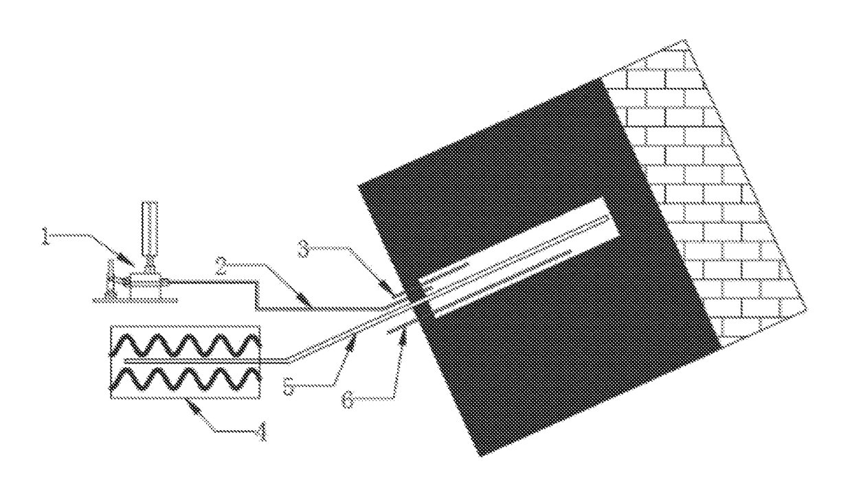
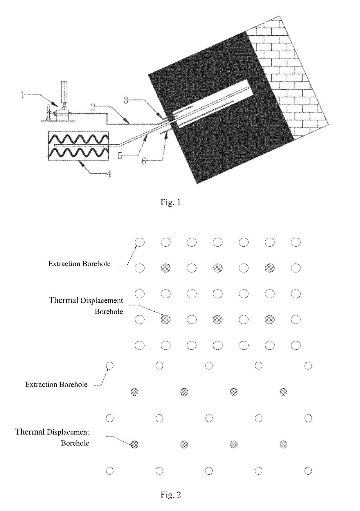
[0017]The method for gas extraction enhanced by thermal displacement in boreholes provided in this disclosure comprises drilling boreholes crossing a coal seam and drilling boreholes down the coal seam:[0018]a. arranging extraction borehole sites at an interval in the coal seam in a way that the extraction boreholes are within the scope of influence of thermal displacement boreholes;[0019]b. sequentially drilling extraction boreholes, sealing the boreholes, and connecting the boreholes into a gas extraction pipe network for gas extraction;[0020]c. arranging a plurality of thermal displacement boreholes among the plurality of extraction boreholes in a way that the thermal displacement boreholes and the extraction boreholes are arranged in a staggered manner, as shown in FIG. 2;[0021]d. sequentially drilling a thermal displacement borehole; inserting a grouting pipe 2, a ret...


PUM


Abstract

A method for thermal-displacement-type strengthened extraction in a drill hole, suitable for efficient gas extraction in a coal mine, the method comprising the following steps: arranging an extraction drill hole and a thermal displacement drill hole at intervals in a coal seam; continuously heating coal in the drill hole to form a stable temperature field by using a heat pipe; and significantly reducing gas adsorption potential by utilizing a heat effect, prompting gas desorption, and strengthening gas extraction. The method enlarges a range of effective pressure relief influence of a single hole, increases an extraction efficiency of gas in a coal seam by more than 40%, is safe, reliable and low-cost, and is easy to operate, saving both time and labor.

Description

CROSS-REFERENCE TO RELATED APPLICATIONS[0001]This application is a national phase entry under 35 U.S.C. §371 of International Patent Application PCT / CN2015 / 096789, filed Dec. 9, 2015, designating the United States of America and published as International Patent Publication WO 2016 / 112759 A1 on Jul. 21, 2016, which claims the benefit under Article 8 of the Patent Cooperation Treaty to Chinese Patent Application Serial No. 201510014227.6, filed Jan. 12, 2015.TECHNICAL FIELD[0002]The application relates to a method for gas extraction enhanced by thermal displacement in boreholes, particularly applicable to efficient gas extraction from a coal seam with high gas concentration and low air permeability under a coal mine.BACKGROUND[0003]An essential means for gas control in the coal mines in, for example, China is gas extraction, mainly gas extraction by drilling boreholes. As the mining work has evolved to deep mining in China, the low air permeability in the coal seams has become a domi...

Claims


Application Information

Patent Timeline
Patent Type & Authority Patents(United States)
IPC IPC(8): E21B43/24E21B33/14E21B43/30
CPCE21B43/24E21B43/30E21B33/14E21B36/00E21B36/04E21F7/00
Inventor LIN, BAIQUANHONG, YIDOUZHU, CHUANJIEYAO, HAO
Owner CHINA UNIV OF MINING & TECH
Learn More