
Wavelength redundancy device and wavelength redundancy method

a wavelength redundancy and wavelength technology, applied in the field of wavelength redundancy devices and wavelength redundancy methods, can solve the problems of increasing the number of multiplexed wavelengths and the insufficient supply of new optical fiber networks, and achieve the effect of reducing the cost and installation space, and effective use of the band

Active Publication Date: 2018-01-16
MITSUBISHI ELECTRIC CORP
View PDF10 Cites 3 Cited by
  • Summary
  • Abstract
  • Description
  • Claims
  • Application Information

AI Technical Summary

Benefits of technology

The invention allows for better use of network resources by eliminating the need for a wavelength redundancy device for each transmission rate. This reduces the cost and space requirements for these devices.

Problems solved by technology

For implementation of high-capacity optical transmission, only increasing the number of multiplexed wavelengths and constructing new optical fiber networks do not sufficiently meet demand.

Method used


Image

  • Wavelength redundancy device and wavelength redundancy method
  • Wavelength redundancy device and wavelength redundancy method
  • Wavelength redundancy device and wavelength redundancy method

Examples


first embodiment

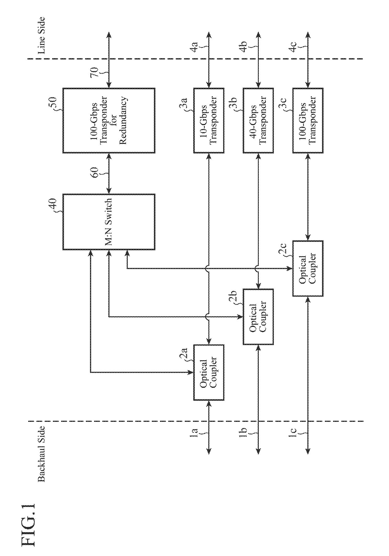
[0023]FIG. 1 shows an exemplary configuration of a terminal device including a wavelength redundancy device according to a first embodiment of the invention.

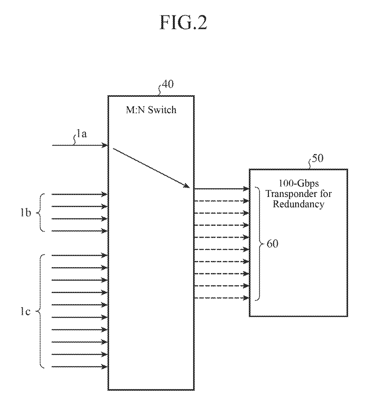
[0024]The terminal device includes optical couplers 2a to 2c that branch client signals 1a to 1c which are transmitted from a backhaul side; a 10-Gbps transponder 3a (working transponder) including one 10-Gbps-based client interface; a 40-Gbps transponder 3b (working transponder) including four 10-Gbps-based client interfaces; a 100-Gbps transponder 3c (working transponder) including ten 10-Gbps-based client interfaces; an M:N switch 40 (selector / switcher) that selectively outputs inputted signals; and a 100-Gbps transponder 50 for redundancy including ten 10-Gbps-based client interfaces. Note that FIG. 1 only shows components related to redundancy and omits components that perform processes such as wavelength multiplexing and amplification.

[0025]The client signal 1a is one 10-Gbps signal to be transmitted to the 10-Gbps transpo...

second embodiment

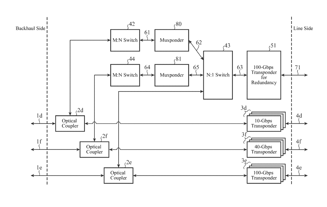
[0059]FIG. 6 shows an exemplary configuration of a terminal device including a wavelength redundancy device according to a second embodiment of the invention.

[0060]The first embodiment shows redundancy for a case in which there are different WDM transmission rates and client signals have the same transmission rate; on the other hand, the second embodiment shows redundancy for a case in which there are different WDM transmission rates and there are also a plurality of types of transmission rates of client signals.

[0061]The terminal device includes optical couplers 2d and 2e that branch client signals 1d and 1e which are transmitted from a backhaul side; d 10-Gbps transponders 3d (working transponders) (d is an integer greater than or equal to 1) each including one 10-Gbps-based client interface; e 100-Gbps transponders 3e (working transponders) (e is an integer greater than or equal to 1) each including one 100-Gbps-based client interface; an M:N switch 42 and an N:1 switch 43 that s...


PUM


Abstract

10-Gbps client signals (1a) to (1c) which are processed by a 10-Gbps transponder (3a), a 40-Gbps transponder (3b), and a 100-Gbps transponder (3c), respectively, are branched by optical couplers (2a) to (2c) into an M:N switch (40). The M:N switch (40) selects a client signal to be made redundant from the branched client signals (1a) to (1c) and outputs the selected client signal to a redundancy 100-Gbps transponder (50) having 10-Gbps-based client interfaces.

Description

FIELD OF THE INVENTION[0001]The invention relates to a wavelength redundancy device in a wavelength multiplexing optical transmission system and a wavelength redundancy method.BACKGROUND OF THE INVENTION[0002]For implementation of high-capacity optical transmission, only increasing the number of multiplexed wavelengths and constructing new optical fiber networks do not sufficiently meet demand. Thus, in recent years, rapid development has proceeded in transmission rate per transponder from conventional 10 Gbps to 40 Gbps, 100 Gbps, and 400 Gbps. For a method of increasing the channel capacity of a submarine cable, an upgrade scheme is common, in which a conventional optical fiber is used and a part of a 10 Gbps band in use is freed up by being taken up by new 40 Gbps and 100 Gbps by migration and is effectively used, or a band that is available in the first place is effectively used.[0003]Due to such technical trends, a wavelength multiplexing optical transmission system including t...

Claims


Application Information

Patent Timeline
Patent Type & Authority Patents(United States)
IPC IPC(8): H04J14/00H04J14/02H04Q11/00H04L69/40
CPCH04Q11/0066H04J14/0297H04Q2011/0081H04Q2011/0016H04J14/0257H04J14/0294
Inventor MAEDA, KENICHI
Owner MITSUBISHI ELECTRIC CORP
Learn More