Diffuser pipe for a gas turbine engine and method for manufacturing same

a technology of diffuser pipe and gas turbine engine, which is applied in the direction of machines/engines, stators, liquid fuel engines, etc., can solve problems such as vibratory stress sensitiveness, and achieve the effect of reducing vibratory stress

Active Publication Date: 2018-01-23
PRATT & WHITNEY CANADA CORP
View PDF34 Cites 9 Cited by
  • Summary
  • Abstract
  • Description
  • Claims
  • Application Information

AI Technical Summary

Benefits of technology

[0004]In one aspect, there is provided a diffuser pipe for a gas turbine engine, the diffuser pipe comprising: a hollow pipe body including: a first end; a second end fluidly connected to the first end; and at least one flattened area proximate to the second end; a ring connected to the second end, the ring being an outlet of the diffuser pipe; and at least one stiffener disposed on the at least one flattened area, the ring and the at least one stiffener reducing vibratory stresses at the second end of the pipe body.

Problems solved by technology

Diffuser pipes are typically made from sheet metal and may be sensitive to vibratory stresses as a result of the engine operation.

Method used


Image

  • Diffuser pipe for a gas turbine engine and method for manufacturing same
  • Diffuser pipe for a gas turbine engine and method for manufacturing same
  • Diffuser pipe for a gas turbine engine and method for manufacturing same

Examples


Embodiment Construction

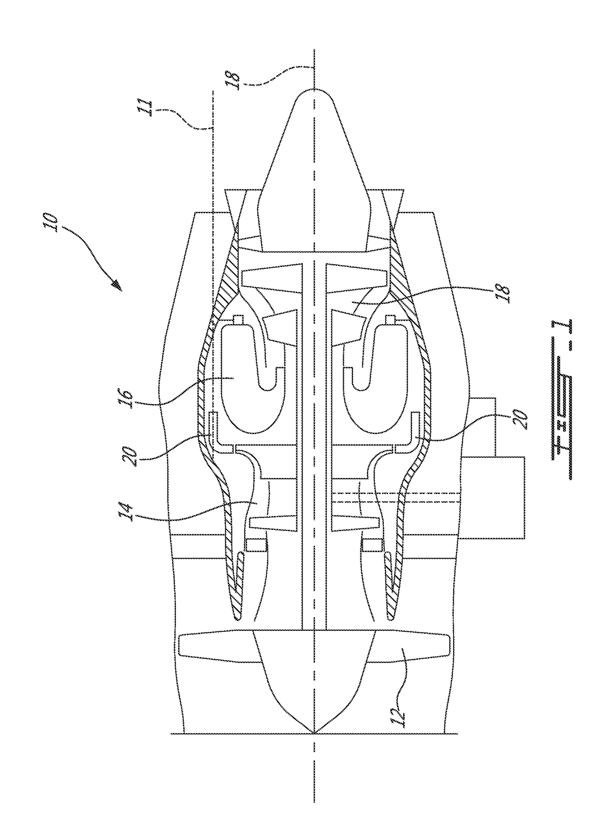
[0012]FIG. 1 illustrates a gas turbine engine 10 of a type preferably provided for use in subsonic flight, generally extending along a longitudinal axis 18. The engine 10 includes in serial flow communication a fan 12 through which ambient air is propelled, a compressor section 14 for pressurizing the air, a combustor 16 in which the compressed air is mixed with fuel and ignited for generating an annular stream of hot combustion gases, and a turbine section 18 for extracting energy from the combustion gases. A number of diffuser pipes 20 are provided for directing flow of compressed air from the centrifugal compressor impeller of the compressor section 14 to an annular chamber or plenum containing the combustor 16. The diffuser pipes 20 are connected of a common diffuser case (not shown).

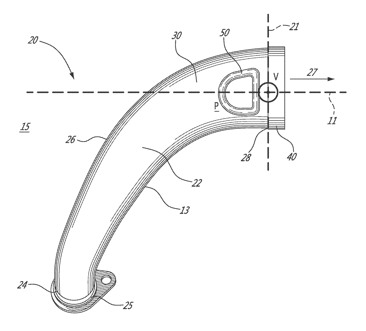
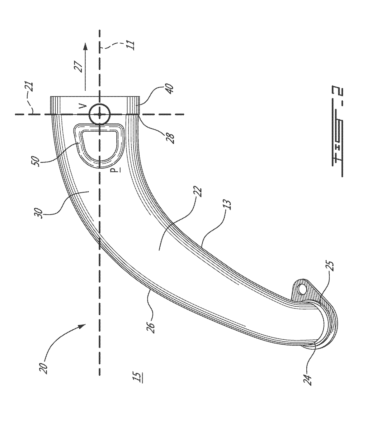
[0013]Referring to FIG. 2, each diffuser pipe 20 has a body 22 made of two formed sheet metals. In the embodiment shown herein, the sheet metals are welded to each other. A weld line 13 is best show...


PUM

PropertyMeasurementUnit
diameter d1aaaaaaaaaa
distanceaaaaaaaaaa

Abstract

A diffuser pipe for a gas turbine engine comprises a hollow pipe body including a first end, a second end fluidly connected to the first end, and at least one flattened area proximate to the second end. A ring is connected to the second end. The ring is an outlet of the diffuser pipe. At least one stiffener is disposed on the at least one flattened area. The ring and the at least one stiffener reduce vibratory stresses at the second end of the pipe body. A method of manufacturing a diffuser pipe of a gas turbine engine is also presented.

Description

RELATED APPLICATIONS[0001]The present application claims priority on U.S. provisional patent application No. 61 / 835,701 filed on Jun. 17, 2013.TECHNICAL FIELD[0002]The application relates generally to gas turbine engines and, more particularly, to diffuser pipes.BACKGROUND OF THE ART[0003]Diffuser pipes are provided in gas turbine engines for directing flow of compressed air from the centrifugal compressor impeller to an annular chamber containing the combustor. Diffuser pipes are typically made from sheet metal and may be sensitive to vibratory stresses as a result of the engine operation.SUMMARY[0004]In one aspect, there is provided a diffuser pipe for a gas turbine engine, the diffuser pipe comprising: a hollow pipe body including: a first end; a second end fluidly connected to the first end; and at least one flattened area proximate to the second end; a ring connected to the second end, the ring being an outlet of the diffuser pipe; and at least one stiffener disposed on the at ...

Claims


Application Information

Patent Timeline
Patent Type & Authority Patents(United States)
IPC IPC(8): F16L9/00F04D29/44F04D29/66F01D9/02
CPCF04D29/441F04D29/668F01D9/02Y10T29/49316
Inventor THERATIL, IGNATIUSABATE, ALDOBALIKE, KRISHNA PRASAD
Owner PRATT & WHITNEY CANADA CORP
Why Eureka
Try Eureka