
Method for producing temporary prosthesis

a dental prosthesis and temporary technology, applied in dental prosthetics, dental prosthetics, dentistry, etc., can solve the problems of occlusal problems, wear easily and have relatively low strength, and the above problems of wear become even more visible, so as to achieve less susceptible to wear and damage

Active Publication Date: 2018-01-30
GC CORP
View PDF20 Cites 2 Cited by
  • Summary
  • Abstract
  • Description
  • Claims
  • Application Information

AI Technical Summary

Benefits of technology

[0020]A method for producing a temporary prosthesis according to the present invention can be easily performed at a dental clinic and at the same time enables fabrication of a temporary prosthesis that is less susceptible to wear and damage.

Problems solved by technology

However, in general, temporary prostheses fabricated using room temperature polymerization resin or conventional paste resin contain filler at a relatively small ratio and therefore tend to wear easily and have relatively low strength.
As such, temporary prostheses have been prone to wear due to occlusion pressure, for example, and cause occlusal problems even when they are used only for a short period of about several days to a week, for example.
Also, depending on circumstances such as the schedule of the patient, there may be cases where temporary prostheses are used for up to a few months, and the above problems due to wear become even more conspicuous in such cases.
Further, regardless of the use period, conventional temporary prostheses are susceptible to damage or breakage that may be caused by the consumption of tough solid food, for example, and as such, there is a demand for a temporary prosthesis having greater strength.
However fabrication procedures using CAD / CAM tend to be more complicated compared to fabrication using room temperature polymerization resin, which can be prepared on site, and the time required for fabrication using CAD / CAM is not much different from fabrication using the lost wax technique.

Method used


Image

  • Method for producing temporary prosthesis
  • Method for producing temporary prosthesis
  • Method for producing temporary prosthesis

Examples


Embodiment Construction

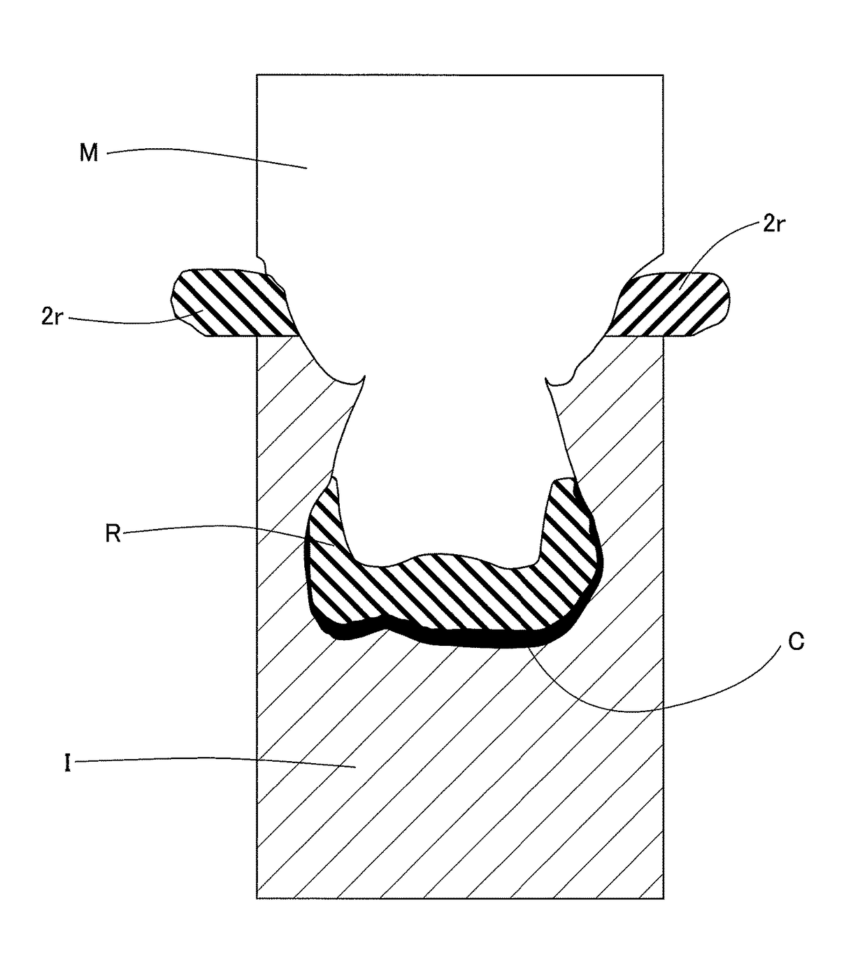
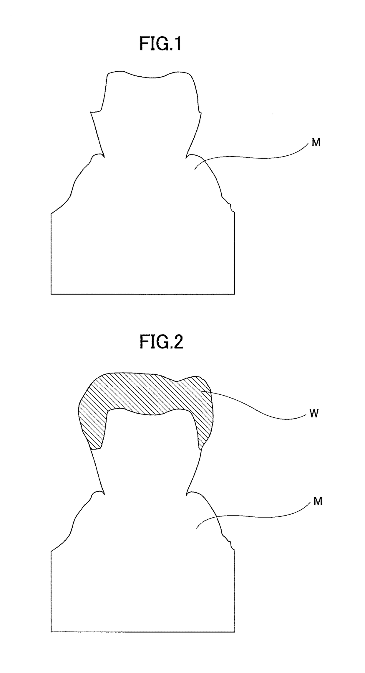
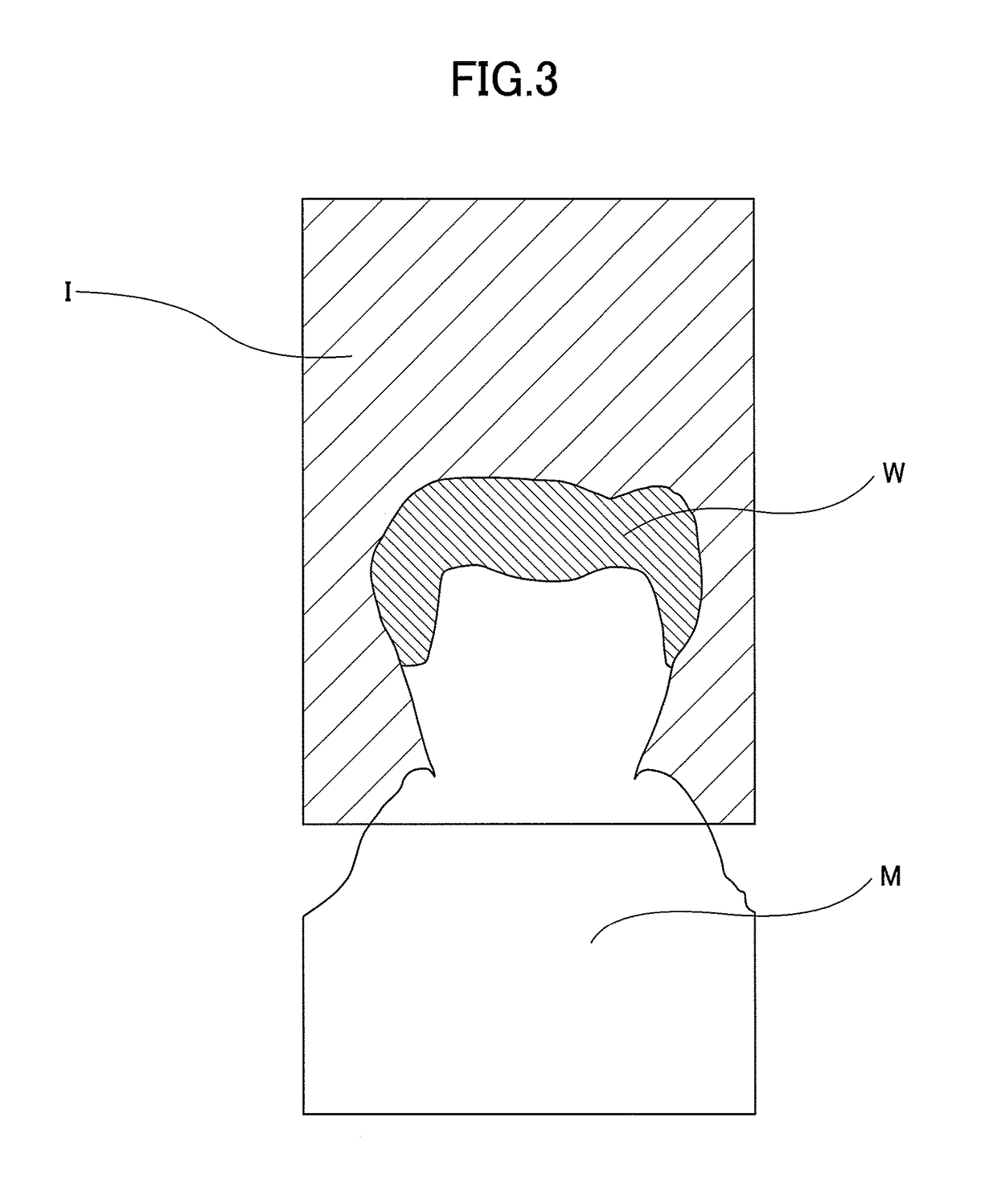
[0037]In the following, methods for producing a temporary prosthesis according to the present invention are described in detail with reference to the accompanying drawings. A first method for producing a temporary prosthesis according to the present invention is described below. First, as illustrated in FIGS. 1 and 15, a prepared tooth model M replicating an oral cavity including a prepared tooth TT that has been arranged into a shape for receiving a temporary prosthesis, namely, a tooth that has been subjected to an abutment tooth or formation of a cavity, is fabricated using a conventional technique. The prepared tooth model M is preferably fabricated using conventional dental plaster but may also be fabricated using other techniques such as polymerization of resin, cutting, 3D printing, and the like, for example.

[0038]Then, using the prepared tooth model M, a prosthesis model W having the same shape as that of the temporary prosthesis to be produced is fabricated with wax, synthe...


PUM

PropertyMeasurementUnit
shapeaaaaaaaaaa
temperatureaaaaaaaaaa
strengthaaaaaaaaaa

Abstract

Provided is a method for producing a temporary prosthesis that can be easily performed at a dental clinic and that at the same time enables fabrication of a temporary prosthesis that is less susceptible to wear and damage. The present invention is achieved by fabricating an occlusal surface with a dental composite resin that has higher strength compared to a conventional room temperature polymerization resin. The method includes fabricating a prosthesis model, using an impression material to take an impression of a prepared tooth model having the prosthesis model mounted thereon, applying a layer of dental composite resin material to a portion that is to become a crown within the impression that has been removed from the prepared tooth model and polymerizing the composite resin material, putting a powder-liquid mixture of a powder-liquid type room temperature polymerization resin into the impression, refitting the prepared tooth model to the impression, and curing the room temperature polymerization resin.

Description

TECHNICAL FIELD[0001]The present invention relates to a method for producing a temporary dental prosthesis to be temporarily inserted until a final definitive prosthesis can be inserted.BACKGROUND ART[0002]Conventionally, in cases where aesthetics resembling a natural tooth are desired in dental prostheses such as crowns and bridges, resin-faced cast crowns, porcelain-baked-faced cast crowns, resin-faced bridges, porcelain-baked bridges, all-ceramic crowns, and the like may be used, for example. Methods for producing such dental prostheses involve making an impression (counterdie of tooth) from the oral cavity of a patient subjected to formation of an abutment tooth, creating a model (replica of tooth) from the impression using resin or plaster, for example, and fabricating the dental prosthesis based on this model using the lost wax technique, for example. The lost wax technique involves, first preparing a wax pattern of a core portion by applying wax in an abutment tooth die, embe...

Claims


Application Information

Patent Timeline
Patent Type & Authority Patents(United States)
IPC IPC(8): A61C13/107A61C5/77A61C5/70A61K6/083A61K6/00A61C5/73A61C13/34A61C13/00A61C13/20
CPCA61C13/0001A61C5/70A61C5/73A61C5/77A61C13/34A61K6/0017A61K6/083C08L33/10A61C13/20A61K6/20A61K6/887
Inventor IKUSHIMA, KEISUKE
Owner GC CORP
Learn More