Clamping system and base, collet chuck and rotary tool therefor and method for mounting the rotary tool in the clamping system

Active Publication Date: 2018-01-30
HAIMER
View PDF45 Cites 5 Cited by
  • Summary
  • Abstract
  • Description
  • Claims
  • Application Information

AI Technical Summary

Benefits of technology

[0025]Additionally the shaft of the rotating tool is inserted into the collet or press collet. This step can be performed before or after inserting the collet into the receiver bore hole of the base element. Eventually the rotating tool is attached in the collet through the clamping nut or alternatively thereto in the press collet through other known attachme

Problems solved by technology

In the field of tool holders with clamping system for rotating tools in particular in the field of heavy duty chip removal over and over again there are problems with respect to strength of the clamping system.
Heavy duty chip removal causes high forces and torques which are transferred by the rotating tool for example a cutter or drill bit through the collet supporting the rotating tool to the base element or the chuck.
During heavy duty ch

Method used


Image

  • Clamping system and base, collet chuck and rotary tool therefor and method for mounting the rotary tool in the clamping system
  • Clamping system and base, collet chuck and rotary tool therefor and method for mounting the rotary tool in the clamping system
  • Clamping system and base, collet chuck and rotary tool therefor and method for mounting the rotary tool in the clamping system

Examples


Example

DETAILED SPECIFICATION

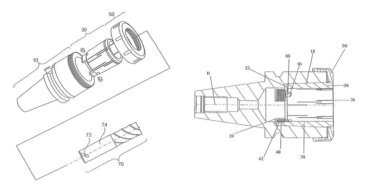
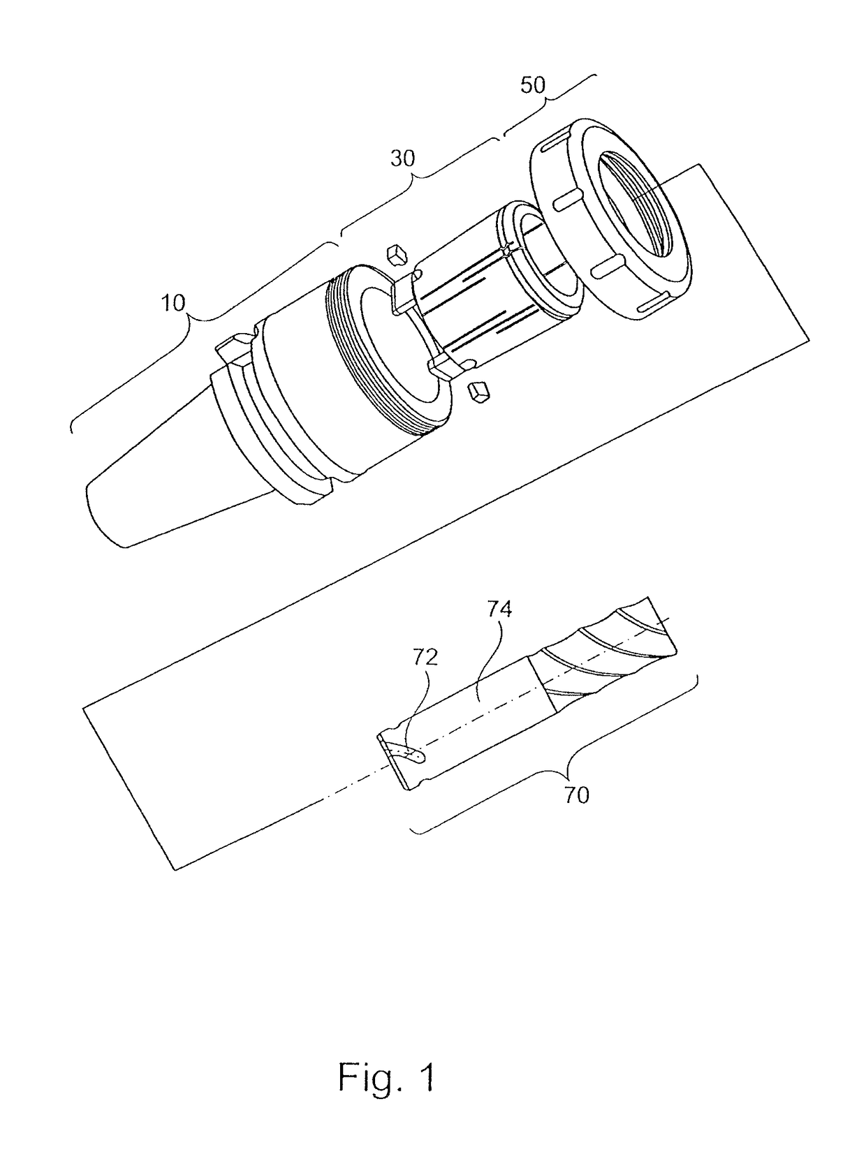
[0067]FIG. 1 illustrates a perspective exploded view of an advantageous embodiment of the clamping system 1 according to the invention. The clamping system 1 includes an advantageous embodiment of a base element 10 which is also illustrated in a lateral sectional view in FIG. 4. In a receiving bore hole 12 which is arranged in this embodiment concentric about a longitudinal axis R of the clamping system 1 a collet 30 is axially insertable from a tool side face 14 of the base element 10. As can be derived from FIG. 1 the illustrated embodiment of the clamping system 1 is arranged rotation symmetrical to the longitudinal axis R. This means that the receiving bore hole 12 of the base element 10 is centrally arranged. Thus the longitudinal axis R of the base element 10, the collet 30, the clamping nut 50 and of the rotating tool 70 is parallel to the rotation axis of the clamping system 1 illustrated in FIG. 1. However, it is also preferred that the receiving bore ...


PUM


Abstract

The invention provides a clamping system (1) for a rotary tool (70), for example a milling cutter or drill. The clamping system (1) includes a base element (10), a collet (30) and a clamping nut (50), said clamping nut (50) friction-locking the rotary tool (70) within the base element (10) with the collet (30). In order to avoid a relative rotation of the base element (10) and the collet (30), the clamping system (1) has a form locking anti-twist protection which blocks a rotation of the collet (30) relative to the base element (10).

Description

CROSS-REFERENCE TO RELATED APPLICATIONS[0001]The present invention is a national phase application of PCT / EP2012 / 003630 which was filed on Aug. 29, 2012 which claims priority to German Patent Application No. 10 2011 113 494.1, filed Sep. 15, 2011.BACKGROUND OF THE INVENTION[0002]The present invention relates to a clamping system, a collet, a base element, a reduction sleeve and a rotating tool The present invention furthermore relates to an installation method for a clamping system.[0003]It is known to support rotating tools like for example drills and in particular milling tools in a clamping device of a machine tool. Such clamping devices include a base element with a coupling side end for reception in a machine tool. Furthermore the base element includes a tool side end with a receiving bore hole that is concentric to a rotation axis of the rotating tool. In this receiving bore hole a shaft of the rotating tool is insertable in axial direction starting from a forward face of the ...

Claims


Application Information

Patent Timeline
IPC IPC(8): B23B31/20B23B31/117B23B31/00B23B31/02
CPCB23B31/20B23B31/02B23B31/1179B23B31/201B23B31/208B23B31/008Y10T409/30952B23B2231/022B23B2231/024B23B2231/026B23B2231/0224B23B2231/0228B23B2231/0232B23B2231/04B23B2231/2005B23B2231/2016B23B2231/2032B23B2231/2035B23B2231/2037B23B2231/2091B23B2240/04B23B2260/026B23B2260/112B23B2265/12Y10T29/49826Y10T279/17418Y10T279/17923B23B31/20125B23B2231/2024
Inventor HAIMER, FRANZKUGLE, WOLFGANG
Owner HAIMER
Why Eureka
Try Eureka