Supercharge Your Innovation With Domain-Expert AI Agents!

Cooling control system

a control system and cooling technology, applied in the field of printing, can solve the problems of dmd chips, current technology is limited, damage can occur, etc., and achieve the effects of preventing condensation on the chip, preventing the chip from overheating, and preventing condensation from developing

Active Publication Date: 2018-01-30
XEROX CORP
View PDF15 Cites 1 Cited by
  • Summary
  • Abstract
  • Description
  • Claims
  • Application Information

AI Technical Summary

Benefits of technology

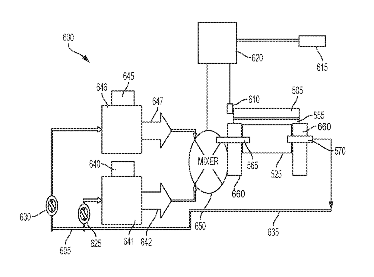
The disclosed embodiments provide an improved cooling control system for electronic chips that can prevent overheating and prevent condensation from developing on the chip. This is achieved by measuring the power of the laser and adjusting the temperature of the fluid circulating through the cooling block accordingly. This method and system can help maintain the proper temperature of the chip, which can improve its performance and reliability.

Problems solved by technology

Damage can occur if the DMD chip (and its internal components) exceeds a critical temperature (approximately 70 degrees Celsius).
As a result current technology is limited.
However, lowering the temperature of coolants is problematic because lower temperatures result in condensation on the DMD chip.
Condensation can foul the chip and / or result in catastrophic damage to the system.

Method used


Image

  • Cooling control system
  • Cooling control system
  • Cooling control system

Examples


Embodiment Construction

[0020]The particular values and configurations discussed in these non-limiting examples can be varied and are cited merely to illustrate at least one embodiment and are not intended to limit the scope thereof.

[0021]The embodiments will now be described more fully hereinafter with reference to the accompanying drawings, in which illustrative embodiments of the invention are shown. The embodiments disclosed herein can be embodied in many different forms and should not be construed as limited to the embodiments set forth herein; rather, these embodiments are provided so that this disclosure will be thorough and complete, and will fully convey the scope of the invention to those skilled in the art. Like numbers refer to like elements throughout. As used herein, the term “and / or” includes any and all combinations of one or more of the associated listed items.

[0022]The particular values and configurations discussed in the following non-limiting examples can be varied and are cited merely ...


PUM


Abstract

A cooling control system and method comprise a power meter for measuring a power of a laser, a temperature controller configured to adjust a temperature of fluid circulating through a cooling block, and a chip connected to the cooling block wherein the temperature controller regulates said temperature of the coolant in order to prevent the chip from overheating or from developing condensation on the chip.

Description

TECHNICAL FIELD[0001]Embodiments are generally related to the field of printing. Embodiments are also related to methods and systems for transferring heat. Embodiments are additionally related to methods and systems for controlling chip temperature. Embodiments are further related to variable cooling control systems where the coolant temperature is a function of power incident on a DMD chip.BACKGROUND[0002]Thermochromic print systems use lasers to selectively deliver energy to a target using a Digital Micromirror Device (DMD). The incident energy (usually laser light) activates thermochromic ink that is distributed on the surface of the target. Damage can occur if the DMD chip (and its internal components) exceeds a critical temperature (approximately 70 degrees Celsius).[0003]As a result current technology is limited. A DMD chip in such a print system can only run at 80% power for approximately 20 seconds before reaching a temperature maximum. It would be advantageous to develop a ...

Claims


Application Information

Patent Timeline
Patent Type & Authority Patents(United States)
IPC IPC(8): B41J29/38B41J29/13B41J29/02B41J2/175B41J29/377G05D23/13B41J2/335G02B7/18B41J2/44B41J2/475
CPCB41J2/3358B41J2/442B41J29/377G05D23/1393G02B7/181B41J2/4753G02B7/1815
Inventor MCCONVILLE, PAUL J.LEFEVRE, JASON M.MOORE, STEVEN R.HERRMANN, DOUGLAS K.
Owner XEROX CORP
Features
  • R&D
  • Intellectual Property
  • Life Sciences
  • Materials
  • Tech Scout
  • Unparalleled Data Quality
  • Higher Quality Content
  • 60% Fewer Hallucinations
Learn More