Piezoelectric power generation module and remote controller

a power generation module and remote controller technology, applied in piezoelectric/electrostrictive/magnetostrictive devices, piezoelectric/electrostriction/magnetostriction machines, instruments, etc., can solve the problem of low energy efficiency ratio of available energy to generated energy, and achieve stable driving, satisfactory energy efficiency, and energy loss encountered while a charge generated by the piezoelectric device moves.

Active Publication Date: 2018-01-30
MURATA MFG CO LTD
View PDF27 Cites 4 Cited by
  • Summary
  • Abstract
  • Description
  • Claims
  • Application Information

AI Technical Summary

Benefits of technology

[0008]With this configuration, since a nonlinear device (e.g., a diode) is not connected in series between the piezoelectric device and the switch control circuit, energy loss encountered while a charge generated by the piezoelectric device moves can be reduced. Further, since a diode that clamps a voltage that is negative with respect to a reference potential is provided in parallel with the piezoelectric device between the piezoelectric device and the switch control circuit, the charge of the piezoelectric device can be quickly released when the voltage across the piezoelectric device becomes lower than or equal to the reference potential. This avoids a problem in that, even when a charge generated in the piezoelectric device for the first time is supplied to a subsequent stage, stable driving cannot be performed due to a decrease in the reference potential at a subsequent time. As a result, the disclosure provides a piezoelectric power generation module enabling stable driving and having satisfactory energy efficiency.
[0012]As a result, the temperature dependency of generated energy and a power generation voltage can be reduced.
[0014]As a result, the temperature dependency after a voltage at the first terminal of the piezoelectric device having become the first threshold voltage can be reduced and, hence, energy efficiency is further increased.
[0016]As a result, a voltage supplied to a stage subsequent to the switch can be controlled more accurately.
[0018]With this configuration, since a nonlinear device (e.g., a diode) is not provided in series between the piezoelectric device and the switch control circuit, energy loss encountered while a charge generated by the piezoelectric device moves can be reduced. Further, since a diode that clamps a voltage that is negative with respect to a reference potential is provided in parallel with the piezoelectric device between the piezoelectric device and the switch control circuit, the charge of the piezoelectric device can be quickly released when the voltage across the piezoelectric device becomes lower than or equal to the reference potential. Hence, a remote controller is provided having stable driving and satisfactory energy efficiency.
[0019]A piezoelectric power generation module and a remote controller is provided having stable driving and satisfactory energy efficiency.

Problems solved by technology

However, energy loss accompanying this movement of charges is generated in the full-wave rectifier circuit and, hence, there is a problem in that the ratio (energy efficiency) of available energy to generated energy is low.

Method used


Image

  • Piezoelectric power generation module and remote controller
  • Piezoelectric power generation module and remote controller
  • Piezoelectric power generation module and remote controller

Examples


first embodiment

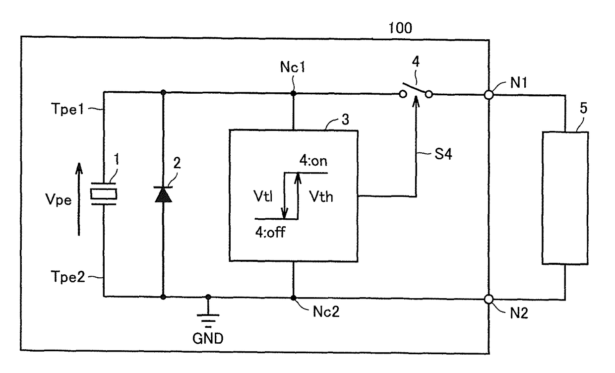
[0030]FIG. 1 is a circuit diagram of a piezoelectric power generation module 100 according to a The terms piezoelectric power generation module and piezoelectric power generation device are used interchangeably herein.

[0031]The piezoelectric power generation module 100 includes a piezoelectric device 1, a diode 2, a load switch control circuit 3, a load switch 4, a first signal line Tpe1, a second signal line Tpe2, an output node N1, and an output node N2.

[0032]A load 5 is connected between the output node N1 and the output node N2. According to an exemplary embodiment, the load 5 can be connected the output nodes N1 and N2 by conductive wiring, for example, and preferably can be connected and disconnected as a removable connector. According to an exemplary embodiment, the load 5 is a processing circuit such as an RF circuit, a microcomputer, or the like. These processing circuits are supplied with a power supply voltage from the output node N1 and the output node N2 of the piezoel...

second embodiment

[0087]FIG. 6 is a circuit diagram of a piezoelectric power generation module 200 according to a

[0088]In FIG. 6, components denoted by the same symbols as those in FIG. 1 have the same configurations or functions of those in FIG. 1 and duplicated descriptions thereof are omitted. The piezoelectric power generation module 200 illustrated in FIG. 6 corresponds to a configuration obtained by replacing the load switch control circuit 3 in the piezoelectric power generation module 100 in FIG. 1 with a load switch control circuit 31.

[0089]FIG. 7 is a circuit diagram of the load switch control circuit 31 in FIG. 6.

[0090]The load switch control circuit 31 in FIG. 7 corresponds to a configuration obtained by replacing the resistor R1 in the load switch control circuit 3 in FIG. 4 by a temperature compensation device R1S.

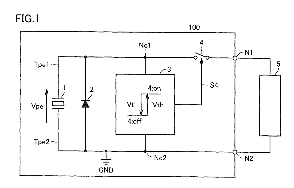
[0091]In the piezoelectric device 1 (refer to FIGS. 2(a)-2(c)) that uses, for example, PZT (lead zirconate titanate) for the piezoelectric body 1C, the composition is usually ...

third embodiment

[0096]FIG. 8 is a circuit diagram of a piezoelectric power generation module 300 according to a

[0097]In FIG. 8, components denoted by the same symbols as those in FIG. 1 have the same configurations or functions of those in FIG. 1 and duplicated descriptions thereof are omitted. The piezoelectric power generation module 300 illustrated in FIG. 8 corresponds to a configuration obtained by connecting a storage capacitor 6 between the first signal line Tpe1 and the second signal line Tpe2 in the piezoelectric power generation module 100 illustrated in FIG. 1. Note that the storage capacitor 6 corresponds to the capacitor device of the present disclosure.

[0098]As described above, the capacitance value and the value of the power generation voltage Vpe of the piezoelectric device 1 vary depending on the surrounding temperature in some cases. For example, in a low surrounding temperature range (temperature range lower than an ordinary temperature of 25° C.), it is feared that an over volta...


PUM


Abstract

A piezoelectric device is connected in parallel with a diode, and outputs a power generation voltage when depressed. When the power generation voltage exceeds a first threshold voltage, a load switch control circuit makes a load switch be conductive, and when the generated voltage becomes lower than a second threshold voltage, the load switch is cut off. Further, when depression is released, the piezoelectric device is discharged by the diode such that the amount of charge remaining in the piezoelectric device becomes zero.

Description

CROSS REFERENCE TO RELATED APPLICATIONS[0001]The present application is a continuation of PCT / JP2014 / 077669 filed Oct. 17, 2014, which claims priority to Japanese Patent Application No. 2014-009596, filed Jan. 22, 2014, the entire contents of each of which are incorporated herein by reference.TECHNICAL FIELD[0002]The present disclosure relates to a piezoelectric power generation module and to a remote controller including the same. For example, the present disclosure relates to a piezoelectric power generation module that converts mechanical energy applied to a piezoelectric device into electrical energy and supplies power to a processing circuit, and relates to a remote controller.BACKGROUND[0003]Currently, there are remote controllers that include a piezoelectric device and do require a battery. For example, Japanese Unexamined Patent Application Publication No. 2011-103729 (Patent Document 1) discloses a configuration of a remote controller which has a power generation capability...

Claims


Application Information

Patent Timeline
Patent Type & Authority Patents(United States)
IPC IPC(8): G08B21/00G08C17/02H02N2/18H01L41/113
CPCH02N2/181G08C17/02H01L41/1134G08C2201/112H10N30/304
Inventor HORIGUCHI, CHIKAHIROTAKAHASHI, KOHEI
Owner MURATA MFG CO LTD
Why Eureka
Try Eureka