Filter with magnet and protective bushing

a filter and magnet technology, applied in the field of filters, can solve the problems of increasing maintenance costs and inconvenience, and achieve the effect of convenient and simple, increasing the length of the flow path of water

Inactive Publication Date: 2018-02-06
SHAO MEIJU
View PDF12 Cites 0 Cited by
  • Summary
  • Abstract
  • Description
  • Claims
  • Application Information

AI Technical Summary

Benefits of technology

[0003]The present invention provides a filter in order to solve the problems that the filter has only single function, cannot filter out both the metal impurities and the non-metal impurities at the same time, and it will need professional service personnel to disassemble the filter to replace the filter cartridge, which is not only inconvenient, but also increases maintenance cost.
[0015]By adopting the above-mentioned technical solution, the following advantages can be obtained. The magnetic bar inside the filter of the present invention can adsorb metal impurities in the water in the channel. The channel is in S shape that can increase the length of the flow path of the water so that the metal impurities in water can be guaranteed to be sufficiently adsorbed by the magnetic bar. The filter screen can filter out the non-metal impurities in water. The exhaust valve can keep the balance between air pressure inside the filter and the air pressure outside the filter, which can ensure that the water can flow out and in smoothly. The filter is attached with an operating handle. If the user wants to disassemble the filter to clear up the metal impurities and non-metal impurities in the filter, he can disassemble the filter by means of the operating handle without the need of professional personnel, which is convenient and simple.

Problems solved by technology

The present invention provides a filter in order to solve the problems that the filter has only single function, cannot filter out both the metal impurities and the non-metal impurities at the same time, and it will need professional service personnel to disassemble the filter to replace the filter cartridge, which is not only inconvenient, but also increases maintenance cost.

Method used


Image

  • Filter with magnet and protective bushing
  • Filter with magnet and protective bushing
  • Filter with magnet and protective bushing

Examples


Embodiment Construction

[0021]The technical solution of the embodiment of the present invention will be described clearly and thoroughly in conjunction with the drawings of the embodiment of the present invention in order to make the object, the technical solutions and advantages of the embodiment of the present invention more clear. Obviously, the embodiments described here are only some embodiments of the present invention, not all the embodiments of the present invention. Based on the described embodiments of the present invention, those ordinarily skilled in the art can obtain other embodiments without creative efforts, and all those embodiments are embraced within the protection scope of the present invention.

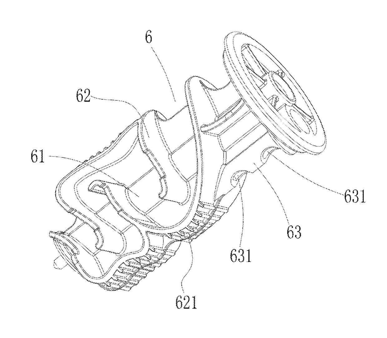
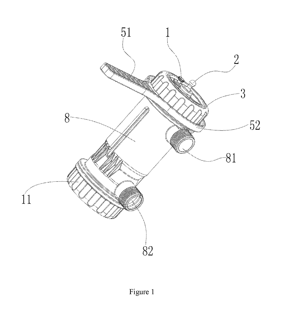
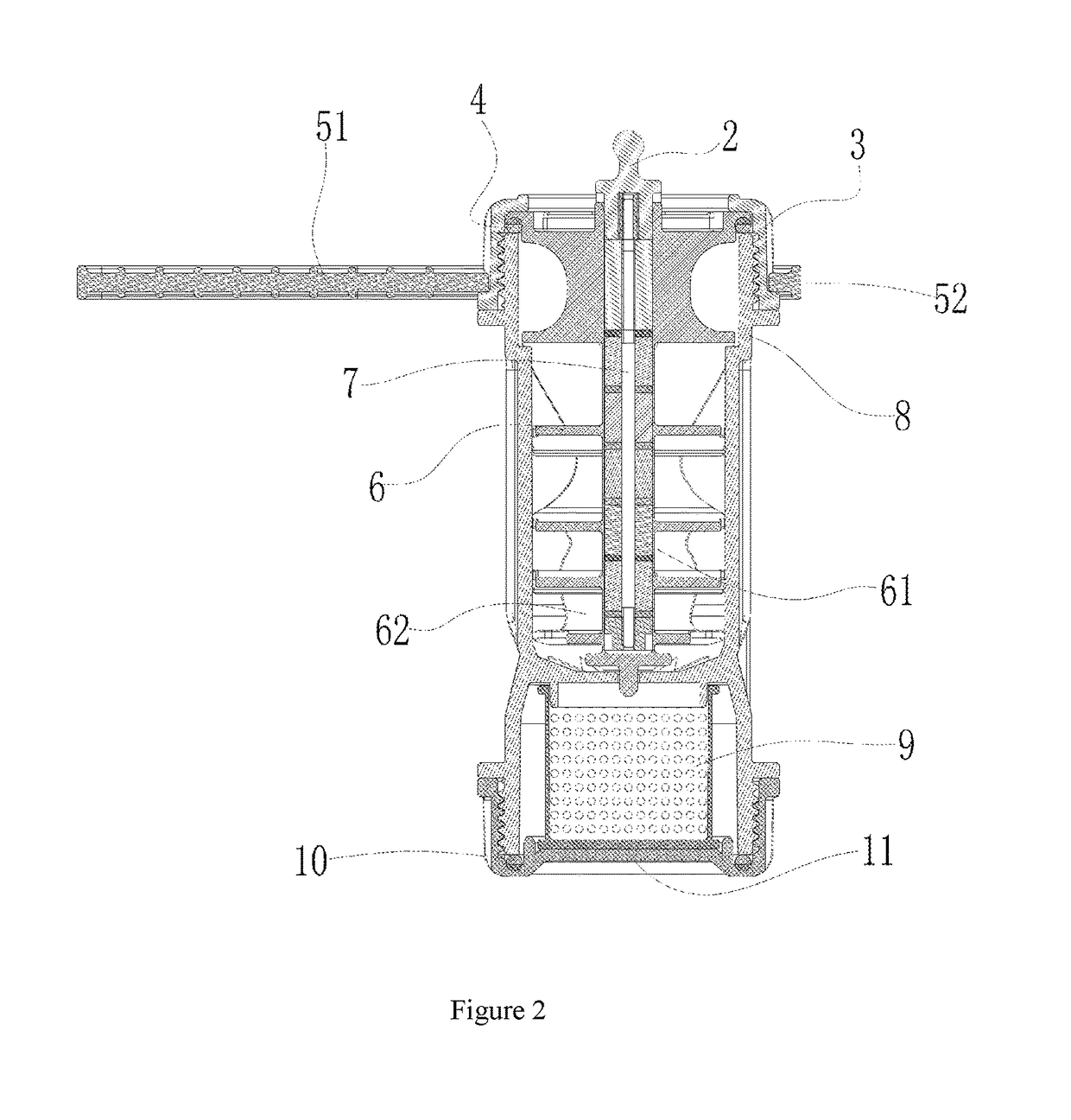
[0022]As shown in FIG. 1 to FIG. 4, the filter comprises a housing, an exhaust valve 1, a magnetic bar nut 2, a first seal ring 4, an operating handle 5, a protective bushing 6, a magnetic bar 7, a filter screen 9 and a second seal ring 10. The housing is made up of an upper cover 3, a body 8 and...


PUM

PropertyMeasurementUnit
temperatureaaaaaaaaaa
shapeaaaaaaaaaa
magneticaaaaaaaaaa

Abstract

The present disclosure relates to a filter, which comprises a housing, a protective bushing, a magnetic bar and a filter screen. The protective bushing, the magnetic bar and the filter screen are disposed in the housing. The protective bushing comprises a cavity and a channel. The channel is disposed along the axial direction of the cavity. The magnetic bar inside the filter adsorbs metal impurities in water in the channel. The shape of the channel increases the length of the flow path of the water so that the metal impurities in the water can be guaranteed to be sufficiently adsorbed by the magnetic bar. The filter screen filters out non-metal impurities in the water. An exhaust valve provided at the top of the protective bushing balances air pressure inside the filter and outside the filter, such that the water can flow out and in smoothly.

Description

FIELD OF THE INVENTION[0001]The present invention relates to the technical field of water cleaning and filtering, in particular relates to a filter.BACKGROUND OF THE INVENTION[0002]Nowadays, many areas employ floor-heating systems to increase room temperature. In the floor heating system, floor-heating pipes are laid under the floor so as to radiate heat in the room. At present, in prior art, the heating water is flowing in the floor heating pipe, that is, the heating water enters through the inlet and then flows out from the outlet of the floor heating pipe. When the floor heating pipe is fabricated, the temperature of the inside water is about 80° C. There are varieties of metal impurities and non-metal impurities mixed in the water. The metal impurities can seriously abrade the floor heating apparatus. The usage life of the floor heating apparatus can be extended by the usage of filter. Most existing filters can only remove metal impurities, but cannot remove non-metal impurities...

Claims


Application Information

Patent Timeline
Patent Type & Authority Patents(United States)
IPC IPC(8): C02F1/48B03C1/30B03C1/28B01D35/06C02F101/10
CPCC02F1/488B01D35/06B03C1/286C02F1/481B03C1/30C02F2101/10B01D2201/347C02F1/001C02F1/484C02F2303/14B01D29/35B01D29/902B01D29/906B01D35/30B01D36/001B03C1/0332B03C1/288B03C2201/18B03C2201/28C02F2101/20
Inventor SHAO, MEIJU
Owner SHAO MEIJU
Why Eureka
Try Eureka