Method and system for simultaneously wirelessly charging portable rechargeable devices based on wireless inductive power transfer with seamless free positioning capability

a wireless inductive power transfer and wireless charging technology, applied in the direction of inductances, high-level techniques, transportation and packaging, etc., can solve the problems of high-resonant wireless power transfer and similar technologies that may not find wide acceptance in a worldwide consumer market, lose seamless free positioning capability, etc., to achieve the effect of maximizing power transfer efficiency

Inactive Publication Date: 2018-02-13
PUDIPEDDI PAVAN
View PDF9 Cites 8 Cited by
  • Summary
  • Abstract
  • Description
  • Claims
  • Application Information

AI Technical Summary

Benefits of technology

[0012]Embodiments of the present invention specifically relate to a system and method for seamlessly and simultaneously wirelessly charging portable rechargeable devices, the system comprising a charging subsystem comprising a controller, an electromagnetic shield for maximization of power transfer efficiency, and a transmitter coil array comprising a first plurality of transmitter coils in juxtaposition and coupled to the electromagnetic shield, and each of a second plurality of transmitter coils overlappingly coupled to at least a pair of the first plurality of transmitter coils in juxtaposition and positioned thereunder, and a controller for sequentially scanning each of the transmitter coils in the transmitter coil array and selectively activating and deactivating the transmitter coils based on the detection of presence of receiver coils positioned at any position relative to the transmitter coils, and a portable chargeable device comprising a receiver coil, wherein the system facilitates maximization of power transfer efficiency while minimization of cross-interference between the transmitter coils in juxtaposition.

Problems solved by technology

One major problem is free positioning of portable devices on a wireless charger thereby facilitating seamless charging of the portable devices thereupon.
However, the seamless free positioning capability is lost on account of physical demarcation between the independent charging systems.
However, the total cost of the equipment turns out to be higher on account of usage of the advanced technology, in addition to the separate communications requirements that needs to be built into the wireless charger.
Thus, highly resonant wireless power transfer and similar technologies may not find wide acceptance in a worldwide consumer market, unless costs are acceptable.
Additionally, the highly resonant wireless power transfer and similar technologies may fail to charge existing mobile phones that already have wireless power capability.
However, as a consequence, the electromagnetic shield provides for a common impedance path thereby resulting in cross-interference amid two or more transmitter coils.
However, the introduction of the gap may have an impact on the efficiency of power transfer, and is thus not recommended.

Method used


Image

  • Method and system for simultaneously wirelessly charging portable rechargeable devices based on wireless inductive power transfer with seamless free positioning capability
  • Method and system for simultaneously wirelessly charging portable rechargeable devices based on wireless inductive power transfer with seamless free positioning capability
  • Method and system for simultaneously wirelessly charging portable rechargeable devices based on wireless inductive power transfer with seamless free positioning capability

Examples


Embodiment Construction

[0028]Various embodiments of a method and system for simultaneously wirelessly charging portable chargeable devices based on wireless inductive power transfer with seamless free positioning capability and improved electromagnetic shield structure are described. In the following detailed description, numerous specific details are set forth to provide a thorough understanding of claimed subject matter. However, it will be understood by those skilled in the art that claimed subject matter may be practiced without these specific details. In other instances, methods, apparatuses or systems that would be known by one of ordinary skill have not been described in detail so as not to obscure claimed subject matter.

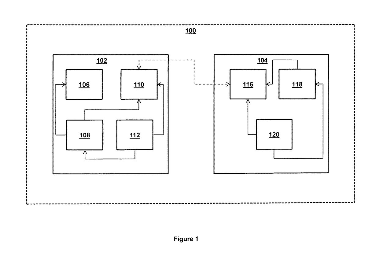
[0029]FIG. 1 depicts a block diagram of a system 100 for simultaneously wirelessly charging portable chargeable / rechargeable devices using wireless inductive power transfer with streamlined and seamless, free positioning capability, according to one or more embodiments.

[0030]The sy...


PUM


Abstract

Embodiments of the present invention specifically relate to a system for seamlessly and simultaneously wirelessly charging portable chargeable devices with free positioning capability and a method therefor. The system comprises a charging subsystem. The charging subsystem comprises an electromagnetic shield for minimization of interference, and a transmitter coil array. The transmitter coil array comprises a first plurality of transmitter coils juxtaposed to each other and coupled to the electromagnetic shield, and a second plurality of transmitter coils, wherein each of the second plurality of transmitter coils is overlappingly coupled to at least a pair of the first plurality of transmitter coils in juxtaposition and positioned thereunder, and at least a controller for scanning the transmitter coils and selectively activating and deactivating the transmitter coils based on the detection of receiver coils positioned at any position relative to the transmitter coils, and a portable chargeable device comprising a receiver coil, wherein the system facilitates minimization of interference between the transmitter coils in juxtaposition.

Description

CROSS-REFERENCE TO RELATED APPLICATIONS[0001]This application claims the benefit of, is a continuation, and is a continuation-in-part of the following provisional applications, which are hereby incorporated by reference in its entirety: U.S. Provisional Patent Application No. 61 / 920,487, captioned “METHOD AND SYSTEM FOR SIMULTANEOUSLY WIRELESSLY CHARGING PORTABLE CHARGEABLE DEVICES BASED ON WIRELESS INDUCTIVE POWER TRANSFER WITH SEAMLESS FREE POSITIONING CAPABILITY” filed Dec. 24, 2013, U.S. Provisional Patent Application No. 61 / 923,785, captioned “METHOD AND SYSTEM FOR AUGMENTING USABILITY IN CONNECTION WITH WIRELESS COMMUNICATION AND POWER MANAGEMENT THEREOF” filed Jan. 6, 2014, and U.S. Provisional Patent Application No. 62 / 006,277, captioned “IMPROVED METHOD AND SYSTEM FOR SIMULTANEOUSLY WIRELESSLY CHARGING PORTABLE CHARGEABLE DEVICES BASED ON WIRELESS INDUCTIVE POWER TRANSFER WITH SEAMLESS FREE POSITIONING CAPABILITY” filed Jun. 2, 2014.BACKGROUND OF THE INVENTION[0002]Field of...

Claims


Application Information

Patent Timeline
Patent Type & Authority Patents(United States)
IPC IPC(8): H02J7/00H02J7/02H02J50/90H02J50/40H02J50/10
CPCH02J7/025H02J50/10H02J50/90H02J50/40Y02D70/00H01F27/22H01F38/14H02J7/00045H02J50/70H01F27/36H02J50/402H01F27/366Y02D30/70
Inventor PUDIPEDDI, PAVANKATRAGADDA, ANANDARAMCHAVA, NAVEEN
Owner PUDIPEDDI PAVAN
Why Eureka
Try Eureka