Spindle apparatus for machine tool

a technology of machine tools and spindles, which is applied in the direction of metal-working apparatus, turning machines, maintenance and safety accessories, etc., can solve the problems of uneven supply quantity of cooling fluid, production cost, and difficulty in integrally forming a headstock

Active Publication Date: 2018-02-20
DMG MORI CO LTD
View PDF13 Cites 2 Cited by
  • Summary
  • Abstract
  • Description
  • Claims
  • Application Information

AI Technical Summary

Benefits of technology

[0010]The disclosed embodiments of the present invention have been developed in view of the above-mentioned and / or other problems in the related art. The disclosed embodiments of the present invention can significantly improve upon existing methods and / or apparatuses.
[0011]The embodiments of the present invention has been made in view of the conventional circumstances, and aim to provide a spindle apparatus for a machine tool capable of reducing a production cost by integrally forming a headstock and reducing adverse influences to processing precision by preventing supply unevenness of a cooling medium to reduce thermal displacement.

Problems solved by technology

In the meantime, it is generally difficult to integrally form a headstock having a motor accommodation section and a cooling medium accumulation part so as to include cooling passages for cooling a motor.
This causes a problem that the production cost arises.
Therefore, the supply quantity of the cooling fluid tends to become uneven especially in the axial direction of the motor.
This raises a concern that the periphery of the motor cannot be cooled evenly.

Method used


Image

  • Spindle apparatus for machine tool
  • Spindle apparatus for machine tool
  • Spindle apparatus for machine tool

Examples


embodiment 1

[0041]FIGS. 1 to 7 are drawings for explaining a spindle apparatus for a machine tool according to Embodiment 1 of the present invention. In this embodiment, the chuck side will be referred to as a machine front side, and when seen from the machine front side, the near side, far side, left side, and right side will be respectively referred to as a front side, the rear side, the left side, and the right side.

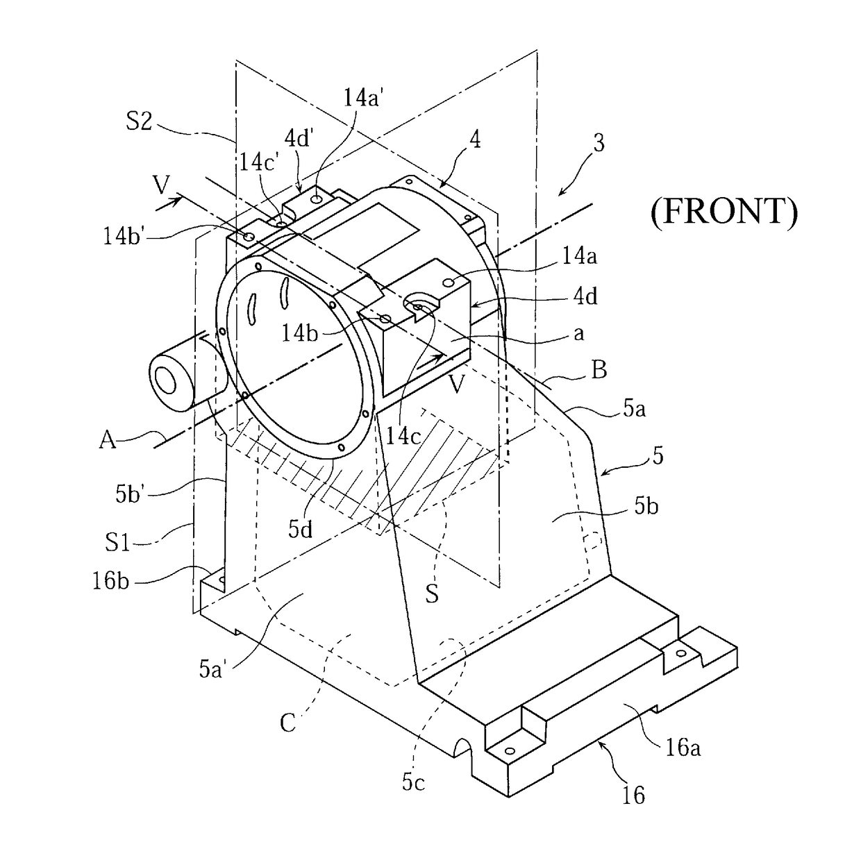
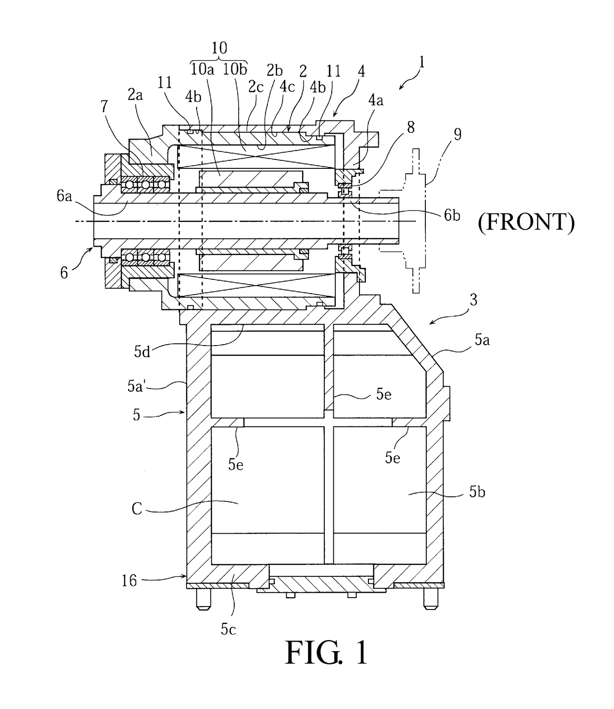
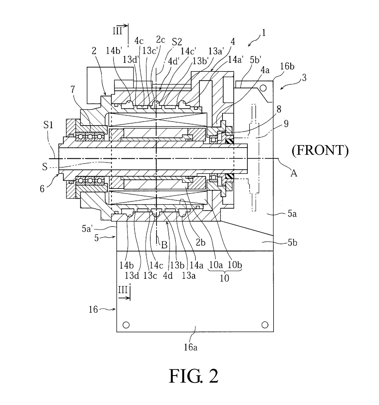
[0042]In the figures, the reference symbol “1” denotes a spindle apparatus fixedly arranged on a bed (not illustrated) for a lathe (machine tool), and the spindle apparatus 1 is equipped with a motor accommodation section 2 for accommodating a motor 10 and a headstock 3.

[0043]The headstock 3 is constituted by a spindle housing 4 in which the motor accommodation section 2 is mounted, an attaching section 16 for attaching the headstock 3 to a bed, and a cooling oil accumulation part (cooling medium accumulation part) 5 integrally casted so as to be positioned between the attaching ...

embodiment 2

[0071]FIGS. 8 to 13 are drawings for explaining Embodiment 2 of the present invention. In the drawings, the same symbol as that in FIGS. 1 to 7 denotes the same or corresponding portion.

[0072]In Embodiment 2, the cooling passage 12 is formed on the outer wall surface 2c of the motor accommodation section 2 by forming ribs 13e, 13f, 13g and 13h which are elongated protrusions on the outer wall surface 2c of the motor accommodation section 2 so as to extend in the circumferential direction thereof and bringing the inner wall surface 4c of the spindle housing 4 into contact with outer surfaces of all of the ribs. In detail, as shown in FIG. 9, the cooling passage 12 is constituted by the passage 12c formed by the ribs 13e and 13f and the passage 12d formed by the ribs 13g and 13h.

[0073]In the passages 12c and 12d, the cooling oils start to flow from the oil supply through-holes 14a and 14b, and cause downward flows C6 and C8 at the intermediate side in the axial direction, respectivel...


PUM


Abstract

A cooling medium accumulation part is integrally formed with a spindle housing and an attaching section between the spindle housing and the attaching section so that at least a width of the cooling medium accumulation part in a direction perpendicular to the spindle is wider than a width of the motor accommodation section in a virtual projection plane obtained by projecting the cooling medium accumulation part in a direction from the spindle housing to the attaching section. A straight oil supply through-holes communicating the cooling medium accumulation part and the cooling passages are formed in a side wall part of the spindle housing.

Description

CROSS-REFERENCE TO RELATED APPLICATIONS[0001]The present application claims priority under 35 U.S.C. 119 to Japanese Patent Application No. 2014-068767, filed on Mar. 28, 2014, the content of which is incorporated herein by reference in its entirety.BACKGROUND OF THE INVENTION[0002]Field of the Invention[0003]The present disclosure relates to a spindle apparatus for a machine tool, and more specifically relates to an improvement of a cooling structure for cooling a periphery of a motor which rotatably drives a spindle.[0004]Description of the Related Art[0005]The following description of related art sets forth the inventors' knowledge of related art and certain problems therein and should not be construed as an admission of knowledge in the prior art.[0006]A spindle apparatus of this kind is provided with a cooling structure for cooling a periphery of a motor to avoid adverse influences to processing precision due to heat generation of a motor which rotatably drives a spindle. For e...

Claims


Application Information

Patent Timeline
Patent Type & Authority Patents(United States)
IPC IPC(8): B23Q11/10B23Q11/12
CPCB23Q11/127Y10T82/2552
Inventor SHIRAI, YUYAKURIYA, TATSUHIKO
Owner DMG MORI CO LTD
Why Eureka
Try Eureka