Unlock instant, AI-driven research and patent intelligence for your innovation.

Rotating device

a rotating device and rotating shaft technology, applied in the direction of rotary stirring mixers, instruments, transportation and packaging, etc., can solve the problems of increasing equipment costs, and achieve the effect of reducing equipment costs and improving working efficiency

Active Publication Date: 2018-02-20
SKYLA CORP HSINCHU SCI PARK BRANCH
View PDF6 Cites 2 Cited by
  • Summary
  • Abstract
  • Description
  • Claims
  • Application Information

AI Technical Summary

Benefits of technology

[0005]The invention provides a rotating device for improving working efficiency and reducing equipment costs.
[0021]Based on the above, in the rotating device of the invention, the driving unit drives the rotating plate to rotate and interfere with the carrier, and drives the carrier to rotate through interference between the rotating plate and the carrier or interference between the base of the driving unit and the carrier. Since the carrier has a rotational inertia when rotating, when the driving unit applies driving force to the rotating plate in the direction opposite to the rotation direction of the carrier, the rotating plate and the carrier rotate relative to each other so as to change the rotation direction of the rotating plate on the carrier. Thus, the user is not required to stop the rotation of the carrier to manually change the rotation direction of the rotating plate. Accordingly, the working efficiency is improved. In addition, the user does not need to dispose an additional driving source for driving the rotating plate on the carrier. Therefore, equipment costs are reduced.

Problems solved by technology

It is also possible to dispose an additional power source (e.g., a motor) in the carrier for driving the rotating plate to rotate so as to change the direction of the rotating plate, but it will increase equipment expenses.

Method used


Image

  • Rotating device
  • Rotating device
  • Rotating device

Examples


Embodiment Construction

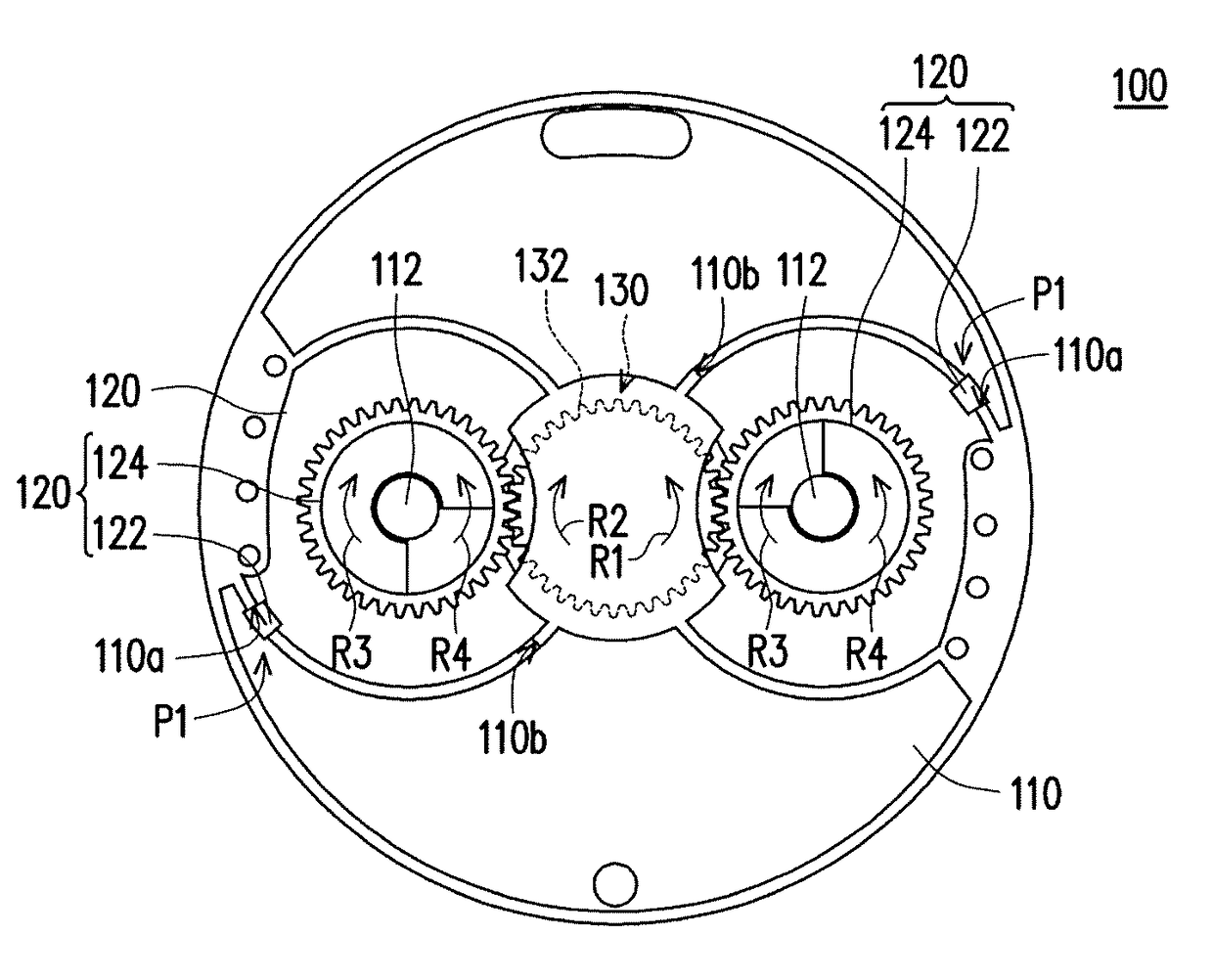
[0037]FIG. 1 is a schematic top view of a rotating device according to an embodiment of the invention. FIG. 2 is a schematic bottom view of a rotating plate of FIG. 1. FIG. 3 is a schematic top view showing part of the components in the rotating device of FIG. 1. Referring to FIG. 1 to FIG. 3, a rotating device 100 of this embodiment is a blood analyzing device, for example, which includes a carrier 110, at least one rotating plate 120 (two are depicted), and a driving unit 130.

[0038]Each rotating plate 120 is rotatably connected with the carrier 110 and is for containing a test liquid (e.g., blood and a corresponding agent). Moreover, each rotating plate 120 has a stopping portion 122, which is a bump, for example. The driving unit 130 includes a rotating member, which is a first gear 132, for example. Each rotating plate 120 has a second gear 124, and the driving unit 130 is engaged with the second gear 124 of each rotating plate 120 through the first gear 132. The rotating member...


PUM

PropertyMeasurementUnit
radiusaaaaaaaaaa
magnetic forceaaaaaaaaaa
elastic forceaaaaaaaaaa

Abstract

A rotating device includes a carrier, a rotating plate, and a driving unit. The rotating plate rotatably connected with a pivot portion of the carrier contains a test liquid. The rotating plate or the driving unit has a stopping portion. When the driving unit drives the rotating plate to rotate so the stopping portion moves to a first position and interferes with the carrier, the driving unit applies driving force to the pivot portion of the carrier along a first rotation direction through the rotating plate. When the carrier rotates along the first rotation direction and the driving unit applies driving force to the rotating plate along a second rotation direction opposite to the first rotation direction, the rotating plate rotates relative to the carrier, the stopping portion moves to a second position and interferes with the carrier, and the driving unit applies driving force to the pivot portion of the carrier along the second rotation direction through the rotating plate.

Description

CROSS-REFERENCE TO RELATED APPLICATION[0001]This application claims the priority benefit of Taiwan application serial no. 105109729, filed on Mar. 28, 2016. The entirety of the above-mentioned patent application is hereby incorporated by reference herein and made a part of this specification.BACKGROUND OF THE INVENTIONField of the Invention[0002]The invention relates to a rotating device and particularly relates to a rotating device for analyzing liquid.Description of Related Art[0003]In terms of the clinical examination of blood components, there are a variety of blood analyzers that can be used for blood analysis. One method for blood analysis is to put blood and an agent in a rotating plate on a carrier and then drive the carrier and the rotating plate thereon to rotate, so as to mix the blood and the agent to cause a chemical reaction, such that components of the blood can be analyzed by means of optical detection.[0004]In order to quickly and sufficiently mix the blood and the ...

Claims


Application Information

Patent Timeline
Patent Type & Authority Patents(United States)
IPC IPC(8): G01N1/38B01F9/00G01N35/00B01F7/14B01F7/10B01F27/73B01F27/75
CPCG01N1/38B01F9/0001B01F9/002B01F9/003B01F9/0021G01N35/00029G01N2035/00524B01F7/10B01F7/14B01F2215/0037G01N2001/386G01N33/5002B01F31/10B01F29/10B01F29/34B01F29/321B01F29/322B01F27/73B01F27/75B01F2101/23
Inventor HO, SZU-HSIEN
Owner SKYLA CORP HSINCHU SCI PARK BRANCH