
Theft-prevention exhibition device and method

a technology of theft prevention and exhibition devices, applied in the field of theft prevention, can solve the problems of limited service life, unsatisfactory user experience, inflexibleness, etc., and achieve the effect of simple wiring and satisfying user experien

Active Publication Date: 2018-02-20
HANGZHOU LANGHONG TECH
View PDF12 Cites 1 Cited by
  • Summary
  • Abstract
  • Description
  • Claims
  • Application Information

AI Technical Summary

Benefits of technology

The present invention provides theft-preventing exhibition devices and methods with the following benefits: satisfactory user experience, simple wiring, easy serviceability in poor environments, and high security. The devices use RFID technology to communicate with each other and do not require any active power source. This allows for a more compact and easy-to-maintain or service second unit while maintaining its security. Overall, the invention provides a better user experience, simplifies the installation process, and enhances safety in adverse environments.

Problems solved by technology

(1) Purely physical theft-prevention technology: this technique is inflexible and provides unsatisfactory user experience;
(2) Electrical connection-based theft-prevention technology: with this technology, all theft-prevention contacts and interfaces are connected to a theft-prevention host by means of electrical connections. This technology also has disadvantages as it requires complicated wiring, has limited service lives, and provides unsatisfactory user experience; and
(3) Active communication-based identification technology: Because the object of identification includes batteries necessary for active communication, the profile of the object is restricted. This technology has disadvantages of being bulky, providing unsatisfactory user experience, and demanding relatively stringent requirements for the environment.

Method used


Image

  • Theft-prevention exhibition device and method
  • Theft-prevention exhibition device and method
  • Theft-prevention exhibition device and method

Examples


example 1

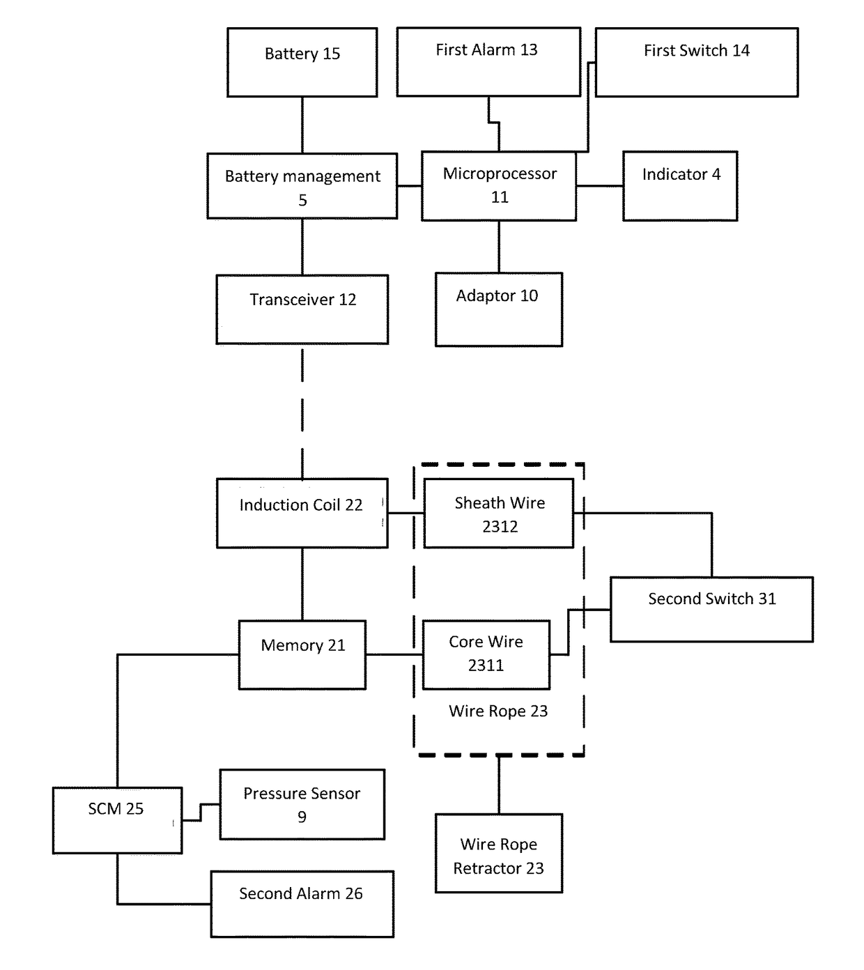
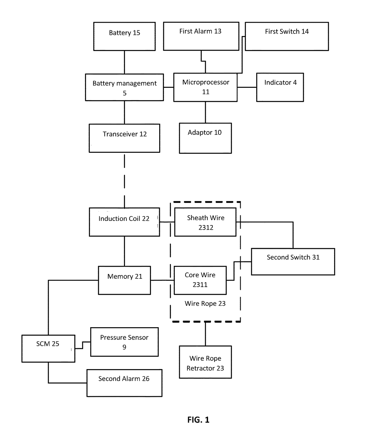
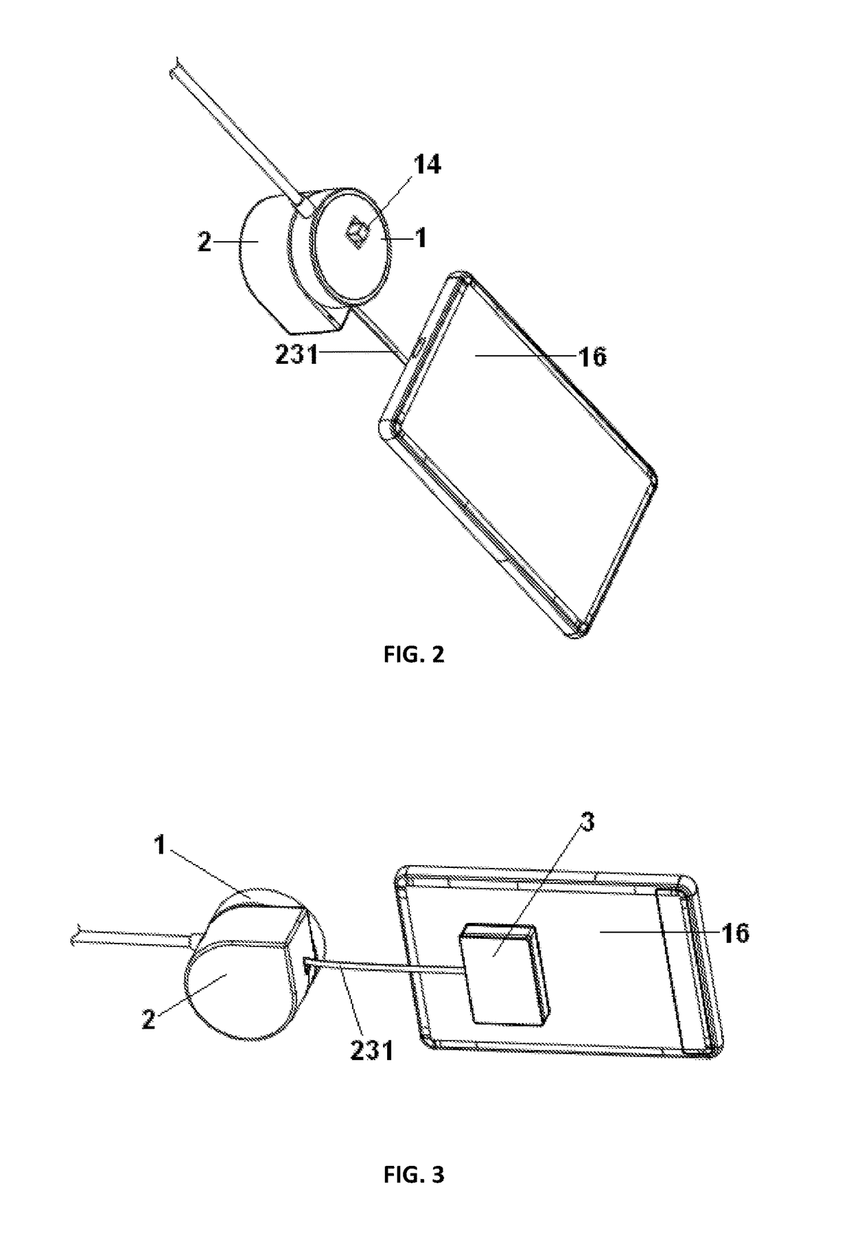
[0047]An embodiment, shown in FIGS. 1, 2, and 3, illustrates a theft-prevention exhibition device, which comprises a first unit 1, a second unit 2, and a connecting plate 3 configured to be connected to a display item (e.g., a mobile phone or a tablet) 16. A microprocessor 11, an RF transceiver 12, a first alarm 13, a first switch 14 protruding out of the first shell, and a rechargeable battery 15 for power supply are provided in the first unit 1.

[0048]A memory 21, a magnetic induction coil 22, and a wire winder (wire retractor) 23 are provided in the second unit 2. A wire rope 231 on the wire winder is connected to a connecting plate 3 (see FIG. 3). The connecting plate 3 may be provided with a second switch 31.

[0049]As shown in FIG. 1, the wire rope 231, which may be a shielded cable, comprises a core wire 2311 and a cover (sheath) wire 2312. An insulating layer is disposed between the core wire 2311 and the sheath wire 2312. The core wire 2311, the second switch 31, the sheath wi...

example 2

[0065]Embodiments of Example 2 comprise all structures and methods as in Embodiments 1 described above. As shown in FIG. 4, this embodiment further comprises an air sac 24, an SCM 25 and a second alarm 26 inside the second unit 2. The cross section of the air sac 24 is in a circular (donut) form; the wire rope 231 penetrates the through-hole 241 at the center of the air sac 24. The wire rope 231 is provided with a platen 8. The air sac 24 is provided with an air pressure sensor 9. The air pressure sensor 9, the memory 21, and the second alarm 26 are connected with the SCM 25.

[0066]This embodiment further comprises the following:

[0067]Customer may pull the wire rope 231 on the wire retractor (i.e., wire winder) 23 when perusing the display unit 16. When the length of the wire rope 231 pulled out of the second unit 2 reaches a preset length M (e.g., M=2 meters), the platen 8 will squeeze the air sac 24 to change the air pressure inside the air sac 24. The air pressure sensor 9 will de...

example 3

[0069]Embodiments in Example 3 comprise all structures and methods as in Embodiments 2. Embodiments 3 may further comprise a step for the correction of the detection signals S(t):

[0070]The SCM 25 will select several sampling values S(t) at a time interval of Δt. The several sampling values are arranged in a time sequence to constitute a detection signal series I(t).

[0071]For each sampling value ES(t) other than the first sampling value and the last sampling value in I(t), use the Formula

[0072]ratio=ES⁡(t1+Δ⁢⁢t)2-ES⁡(t1)2ES⁡(t1)2-ES⁡(t1-Δ⁢⁢t)2

to calculate a stability coefficient ratio.

[0073]The SCM 25 contains preset increasing threshold values 0.5, 1 and 1.65.

[0074]If the stability coefficient ratio is within the range of [1−A1,1+A1], the sampling values ES(t) are to be corrected to B1*ES(t), wherein B1 is 0.3.

[0075]If the stability coefficient ratio within the range of (0.6,1−A1) or (1+A1,1.65), the sampling values ES(t) are to be corrected to B2*ES(t), wherein B2 is 0.5.

[0076]Use ...


PUM


Abstract

A theft-prevention exhibition device includes a first unit, which comprises a microprocessor, a radiofrequency (RF) transceiver, a first alarm, a first switch, a power source, wherein the microprocessor is electrically connected with the RF transceiver, the first alarm, and the first switch; a second unit, which comprises a memory, a magnetic induction coil, and a wire retractor; a connecting plate adapted to be connected to a display item, wherein the connecting plate comprises a second switch; a wire rope spooled on the wire retractor and connected to the connecting plate, wherein the wire rope connects with the second switch, the memory, and the magnetic induction coil to form a circuit.

Description

CROSS REFERENCE TO RELATED APPLICATIONS[0001]This application claims the priority of Chinese Patent Application No. 201610680173.1, filed on Aug. 16, 2016, the disclosure of which is incorporated by reference in its entirety.BACKGROUND OF INVENTIONField of the Invention[0002]The present invention relates to the theft-prevention technical field of wholesale digital products, in particular to theft-prevention exhibition devices and methods.Background Art[0003]Normally, customers prefer to experience electronic equipment that interests them prior to purchases. Therefore, retails of electronic devices have gradually transformed from enclosed exhibition / display to an open display environment such that the user can touch and play with the devices (e.g., cell phones and pads).[0004]Currently, the following theft-prevention technologies for retail experience are available on the market:[0005](1) Purely physical theft-prevention technology: this technique is inflexible and provides unsatisfa...

Claims


Application Information

Patent Timeline
Patent Type & Authority Patents(United States)
IPC IPC(8): G08B13/14
CPCG08B13/1445G08B13/1427G08B13/1454G08B13/1472G08B21/0275
Inventor XIN, HONG
Owner HANGZHOU LANGHONG TECH
Learn More