Magnet chuck

a magnet chuck and chuck technology, applied in the field of magnet chucks, can solve the problems of not easy to produce such a large attracting force, and achieve the effects of reducing stress on the magnet chuck, preventing separation or falling off of the workpiece from the magnet chuck, and reducing vibrations of the magnet chuck

Active Publication Date: 2018-02-27
SMC CORP
View PDF5 Cites 0 Cited by
  • Summary
  • Abstract
  • Description
  • Claims
  • Application Information

AI Technical Summary

Benefits of technology

[0013]From the fact that the attractive force is made greater in the foregoing manner, even in the case that the workpiece is a thin-walled member (e.g., a thin steel plate) and that it is easy for magnetic saturation to occur in the interior thereof, the workpiece can effectively be attracted magnetically and sufficiently retained. Stated otherwise, the present invention is particularly effective when the thickness of the workpiece is small.
[0029]In such a configuration, preferably, a plurality of buffering members are provided, and projecting thicknesses of the buffering members from the magnet cover differ mutually from each other. In this case, an attracting force with respect to the workpiece can be altered by exchanging the buffering member. The region at which the buffering member projects from the magnet cover interferes with the workpiece. Accordingly, as the projecting thickness of the buffering member from the magnet cover becomes greater, the distance between the permanent magnet and the workpiece also is increased. As a result, it becomes more difficult for the influence of the magnetic force from the permanent magnet to act on the workpiece.

Problems solved by technology

However, in particular, in the case that the workpiece is a thin plate, since magnetic saturation occurs in the interior of the workpiece, it is not easy for such a large attracting force to be produced.

Method used


Image

  • Magnet chuck
  • Magnet chuck
  • Magnet chuck

Examples


Embodiment Construction

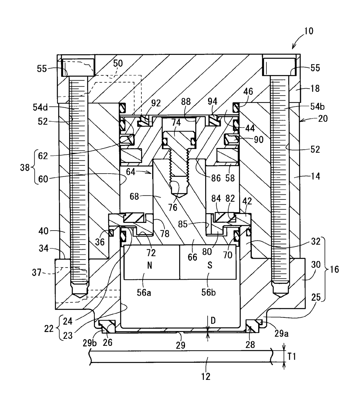
[0050]Preferred embodiments of a magnet chuck according to the present invention will be described in detail below with reference to the accompanying drawings. In the following description, the terms “up” and “down” correspond to the up and down directions in FIGS. 1, 3, and 4. Further, in the present embodiment, a case is exemplified in which compressed air is used as a working fluid.

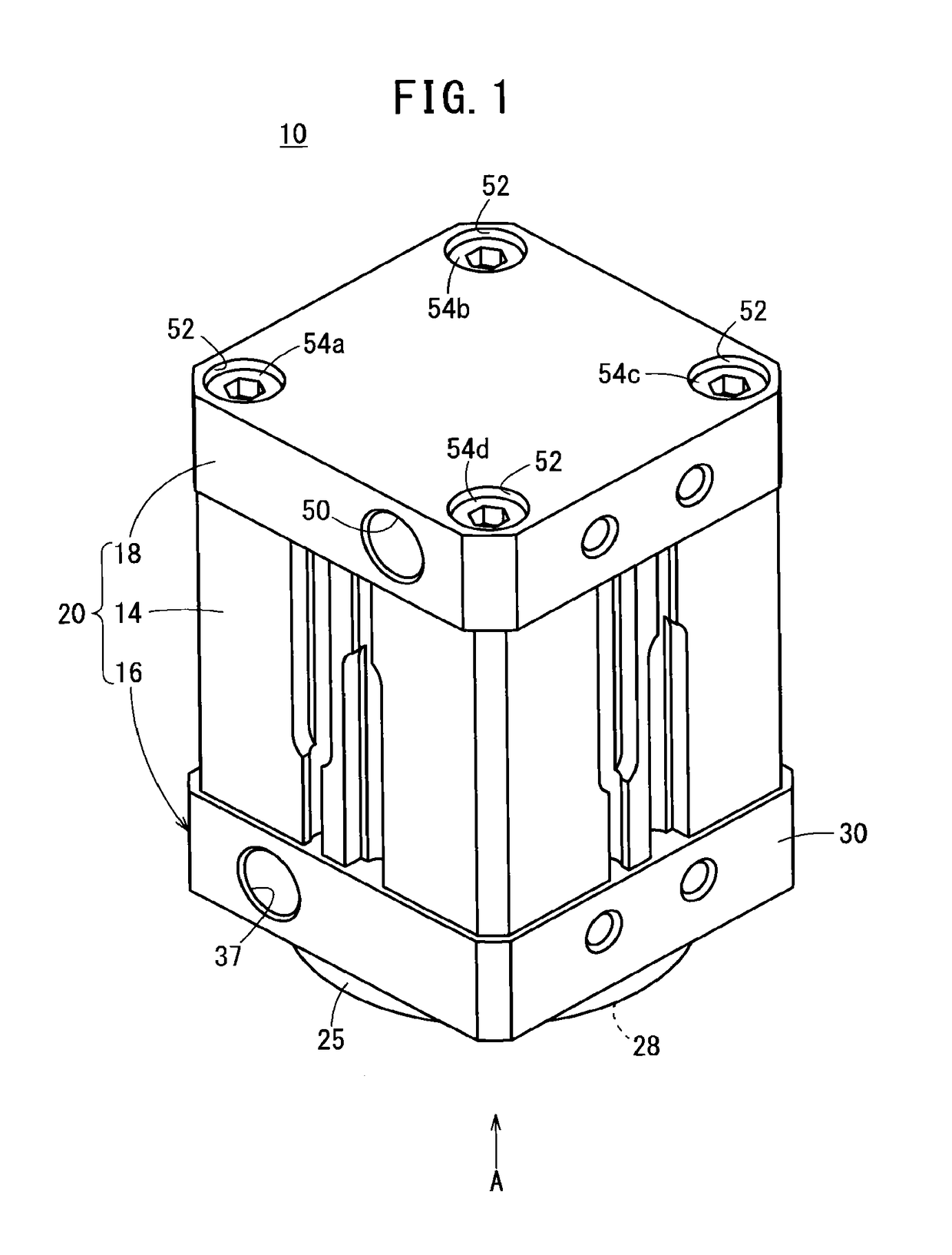
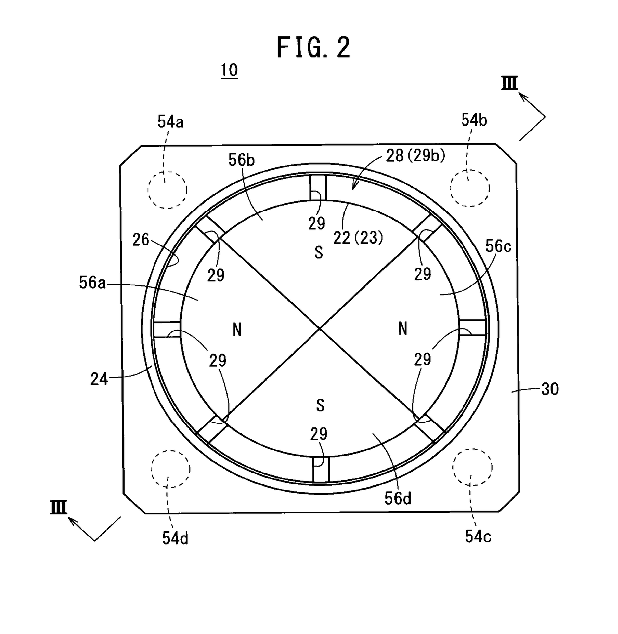
[0051]FIGS. 1 through 3 are, respectively, an outline perspective view of essential components of a magnet chuck 10 according to an embodiment of the present invention, a plan view as seen from the direction of the arrow A in FIG. 1, and a cross-sectional view taken along line III-III of FIG. 2. The magnet chuck 10 attracts and retains a workpiece 12 shown in FIG. 3. Of course, the workpiece 12 is constituted from a ferromagnetic material, and as a detailed example thereof, a thin steel plate may be cited. A thickness T1 of the workpiece 12 is on the order of 0.5 to 2 mm, for example, and typically is ...


PUM

PropertyMeasurementUnit
thickness T1aaaaaaaaaa
central angleaaaaaaaaaa

Abstract

A magnet chuck includes, for example, four permanent magnets of a first permanent magnet through a fourth permanent magnet, serving as an attracting and retaining member for attracting and retaining a workpiece. In the first permanent magnet and the third permanent magnet, the magnetic polarity of a workpiece magnetic attracting surface facing the workpiece is of an N-polarity. On the other hand, in the second permanent magnet and the fourth permanent magnet, the magnetic polarity of a workpiece magnetic attracting surface is of an S-polarity. More specifically, in this case, combinations of the N-pole and the S-pole on the workpiece magnet attracting surface are formed in two pairs, and the N-pole and the S-pole, which are of different polarities, are adjacent to one another.

Description

CROSS-REFERENCE TO RELATED APPLICATIONS[0001]This application is based upon and claims the benefit of priority from Japanese Patent Applications No. 2014-264721 filed on Dec. 26, 2014 and No. 2015-117229 filed on Jun. 10, 2015, the contents all of which are incorporated herein by reference.BACKGROUND OF THE INVENTION[0002]Field of the Invention[0003]The present invention relates to a magnet chuck that attracts and retains a workpiece by the magnetic force of a permanent magnet.[0004]Description of the Related Art[0005]A magnet chuck includes either one of an electromagnet or a permanent magnet. In the case of an electromagnet, a magnetic force is generated by starting supply of current (i.e., energizing) to the electromagnet, and the workpiece is attracted and retained by the magnetic force. Further, when supply of current is stopped, the magnetic force disappears, and as a result, the workpiece is released.[0006]On the other hand, in the case of a permanent magnet, for example, as ...

Claims


Application Information

Patent Timeline
Patent Type & Authority Patents(United States)
IPC IPC(8): B66C1/04B23Q3/154H01F7/02B25B11/00
CPCH01F7/0252B23Q3/1546H01F7/0257B66C1/04B25B11/002
Inventor YAJIMA, HISASHISASAKI, TSUYOSHIKANDA, KOUICHIROU
Owner SMC CORP
Why Eureka
Try Eureka