Fuel injection control device and fuel injection system

a control device and fuel injection technology, applied in mechanical equipment, electric control, machines/engines, etc., can solve the problems of fuel not being injected into the internal combustion engine, the current value of the pick-up device is reduced, and the injector cannot be opened

Active Publication Date: 2020-05-12
DENSO CORP
View PDF13 Cites 0 Cited by
  • Summary
  • Abstract
  • Description
  • Claims
  • Application Information

AI Technical Summary

Benefits of technology

[0008]It is an object of the present disclosure to provide a fuel injection control device which can open an injector and control a fuel injection quantity when a voltage of a battery is lowered.
[0010]According to the present aspect, when the battery voltage decreases, the electronic controller energizes the coil by applying the boost voltage to the coil and executes the correction of the current value to increase a maximum value of the current flowing through the coil, thereby increasing the attractive force generated at the coil. In other words, the attractive force decreased due to a decrease of the battery voltage is corrected by the correction, and the attractive force can be increased to a force required to open the injector. Thus, when a power voltage of the battery decreases, the fuel injection can be controlled by opening the injector.

Problems solved by technology

However, when the above fuel injection quantity control is executed in a case where the voltage of the battery decreases, the pickup current value decreases, and it is possible that the attractive force sufficient to open the injector is not generated.
Then, when the electric controller instructs to open the injector, the injector cannot be opened since the attractive force that is sufficient is not generated at the coil.
Thus, the fuel cannot be injected into the internal combustion engine with the injection quantity that is requested.

Method used


Image

  • Fuel injection control device and fuel injection system
  • Fuel injection control device and fuel injection system
  • Fuel injection control device and fuel injection system

Examples


first embodiment

[0025]Embodiments of the present disclosure will be described hereafter referring to drawings. The substantially same parts or components as those in the embodiments are indicated with the same reference numerals and the same descriptions may be omitted.

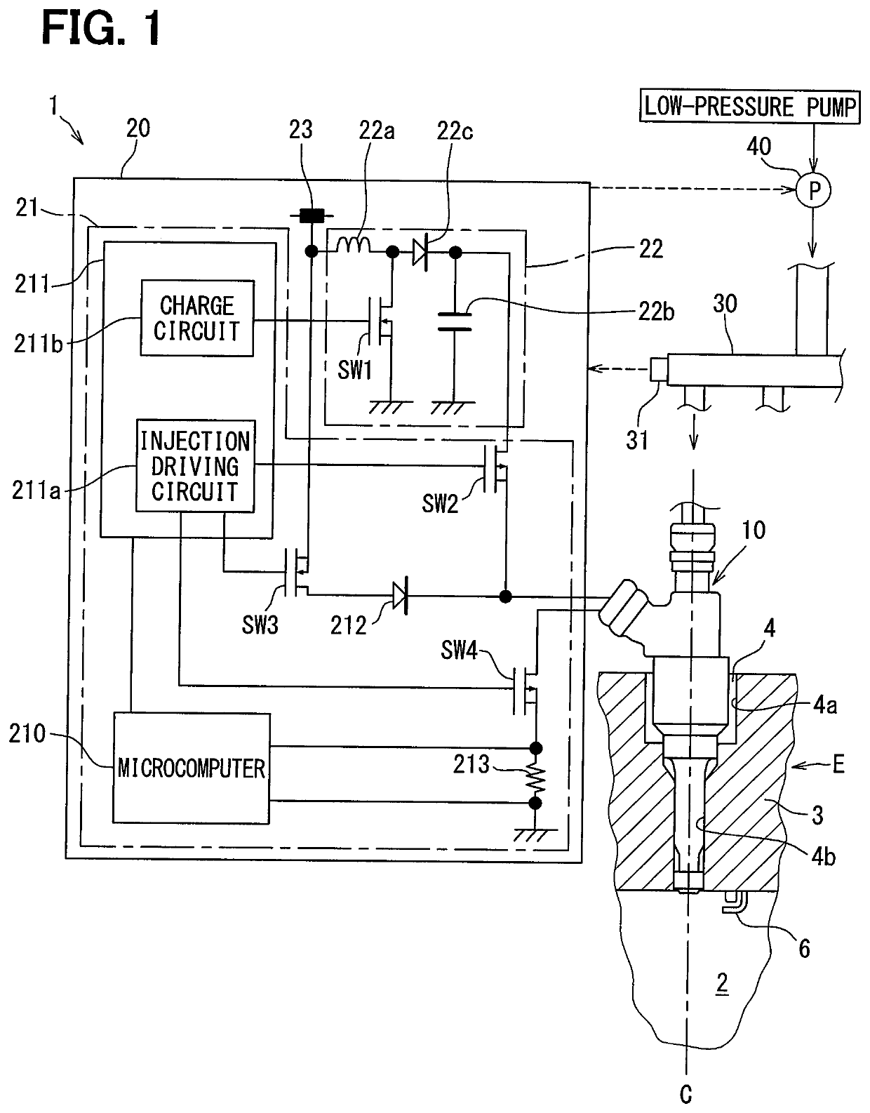
[0026]As shown in FIG. 1, a fuel injection system 1 controls an opening and closing of an injector 10 by a fuel injection control device 20 and controls a fuel injection of the injector 10 to a combustion chamber 2 of an internal combustion engine E.

[0027]The injector 10 is attached to the internal combustion engine E (gasoline engine) of an ignition type. The injector 10 directly injects a fuel into the combustion chamber 2 of the internal combustion engine E. Specifically, an attachment hole 4 into which the injector 10 is inserted is coaxially located with a cylinder head 3 that defines the combustion chamber 2. In other words, the attachment hole 4 includes an axial line that overlaps an axial line C of a cylinder including the c...

second embodiment

[0085]Hereafter, the fuel injection control device according to a second embodiment of the present disclosure will be described. The substantially same configurations as the first embodiment and the same description will be omitted.

[0086]FIG. 6 is a flowchart showing the fuel injection control according to the second embodiment. The microcomputer 210 of the electronic controller 21 according to the second embodiment functions as the valve-opening control unit, the open valve maintenance control unit and the current correction control unit.

[0087]The second embodiment differs from the first embodiment that the current correction quantity Iα with respect to the peak current value Ipeak is calculated according to the decreasing quantity ΔV of the battery voltage Vbatt and the fuel pressure of the fuel supplied into the injector 10 at S20A in the current correction control unit.

[0088]The electronic controller 21 according to the second embodiment previously establishes a map indicating a...

third embodiment

[0094]Hereafter, the fuel injection control device according to a third embodiment of the present disclosure will be described. The substantially same configurations as the first embodiment and the second embodiment and the same description will be omitted.

[0095]According to the third embodiment that is different from the first and second embodiments, the microcomputer 210 of the electronic controller 21 functions as the valve-opening control unit, the open valve maintenance control unit and a current continuation control unit. In operations from S70 to S74 in S7 in the current continuation control unit, the boost voltage Vboost is controlled by a duty control in a predetermined time interval without executing the correction of the peak current value Ipeak. A control that continuously controls an average value of the current flowing through the coil 13 at the peak current value Ipeak is executed. In this case, the current is continued to be in a state that the average value of the c...


PUM


Abstract

A fuel injection control device includes an electric controller controlling an opening and closing of an injector by energizing a coil in the injector, and a booster circuit boosting a battery voltage to generate a boost voltage. The electric controller includes a valve-opening control unit applying the boost voltage and then applying the battery voltage to the coil to execute a valve-opening control to generate a required valve-opening force, an open valve maintenance control unit applying the battery voltage to the coil to execute an open valve maintenance control to generate an open valve maintenance force and is smaller the required valve-opening force, after the valve-opening control, and a current correction control unit executing a current correction control to correct a maximum value of a current flowing through the coil when the boost voltage is applied in the valve-opening control, according to a decreasing quantity of the battery voltage.

Description

CROSS REFERENCE TO RELATED APPLICATION[0001]This application is the U.S. national phase of International Application No. PCT / JP2016 / 077772 filed Sep. 21, 2016, which designated the U.S. and claims priority to Japanese Patent Application No. 2015-217817 filed on Nov. 5, 2015, the entire contents of each of which are incorporated herein by reference.TECHNICAL FIELD[0002]The present disclosure relates to a fuel injection control device which controls a quantity of a fuel injected into an internal combustion engine.BACKGROUND ART[0003]Conventionally, an injector according to Patent Literature 1 includes a stator core that generates an attractive force while a coil is energized, and a movable core that is attracted by the stator core and moves together with a valve body. An electric controller controls an energization of the coil to open the injector. The electric controller controls a time that the injector is being opened, that is, the electric controller controls an injection time of ...

Claims


Application Information

Patent Timeline
Patent Type & Authority Patents(United States)
IPC IPC(8): F02D41/20F02M51/00F02D41/34F02M51/06F02D41/40F02M45/08F02M61/10F02M61/16
CPCF02M61/10F02M45/083F02M51/06F02D41/402F02M51/00F02D41/34F02D41/40F02M51/0653F02M61/161F02D41/20F02D2041/2058F02D2041/2006Y02T10/44F02D2200/503F02M2200/21F02D2041/2051F02M2200/247F02D2041/2013F02M61/16Y02T10/40
Inventor SATAKE, NOBUYUKI
Owner DENSO CORP
Why Eureka
Try Eureka