Photovoltaic mounting system

a technology of photovoltaic energy and mounting system, which is applied in the direction of heat collector mounting/support, light and heating apparatus, sustainable buildings, etc., can solve the problems of labor, crew size and installation time, and labor costs associated with solar systems, and achieve the effect of reducing installation time, hardware costs, and part counts

Active Publication Date: 2018-02-27
TESLA INC
View PDF30 Cites 10 Cited by
  • Summary
  • Abstract
  • Description
  • Claims
  • Application Information

AI Technical Summary

Benefits of technology

[0009]The present invention provides a new and improved mounting system for roof-based photovoltaic modules, and in particular those installed on composite shingle roofs, that reduces installation times, hardware costs, and part counts relative to existing mounting solutions.
[0010]In various embodiments of the invention, these benefits are attained with a two-piece mounting system. The system may have a substantially planar base portion with at least one through-hole for accommodating a lag bolt or other mechanical fastener to secure the base portion to a roof surface and a pivot point protruding away from a roof-facing surface. A movable portion may be coupled to the base portion by the pivot point, and have a slot formed therein, wherein the pivot point passes through the slot, allowing the movable portion to move about the pivot point laterally and rotationally. A fastener may be attached to the pivot point to secure the movable portion in a particular position with respect to the base portion. A two-sided coupler attached to the movable portion by a support post, wherein a distance between the support post and the coupler is adjustable. In various embodiments, the system also includes a layer of butyl or other sealing adhesive that provides a seal between the underside of the base portion and a roof surface around the hole containing the lag bolt that attaches the base portion to the roof, thereby preventing the ingress of water via the roof penetration.
[0013]Other embodiments may provide a photovoltaic mounting system having a lower pyramid having a bottom surface, a top surface, and a pair of inwardly sloping walls connecting the bottom surface to the top surface, and an upper pyramid, having a bottom surface matching the width of and resting at least in part of the top surface of the base portion, a top surface, a pair of inwardly sloping walls angled at the same angle as the pair of inwardly sloping walls of the base portion. A pair of collinear slots formed in the top and bottom surfaces of the upper pyramid allows an adjustment bolt to pass through so that the upper pyramid can move with respect to the lower pyramid while remaining attached thereto. A photovoltaic module coupling device may be connected to the upper pyramid for supporting the frames of at least two adjacent photovoltaic modules.

Problems solved by technology

Solar mounting systems in particular effect not only hard costs associated with a solar system, but also potentially soft costs such as labor, crew size and installation times.
While functional, rail-based systems utilize large amounts of material and take a relatively long time to install.
Second, because they are relatively large compared to the size of a drill hole, when used in solar installations, they cover up errant drill holes that miss a roof rafter.
These advantages, however, come at a cost.
First, flashings are expensive.
Every roofing nail that is removed to accommodate a flashing is a potential point of ingress for water requiring additional sealing.
Third, because of the modifications that must be made to the roof to accommodate a flashing, all flashings and mounting supports have to be installed first.
This creates an installation bottleneck because all flashings must be correctly positioned and permanently installed before any solar panels can be placed.

Method used


Image

  • Photovoltaic mounting system
  • Photovoltaic mounting system
  • Photovoltaic mounting system

Examples


Embodiment Construction

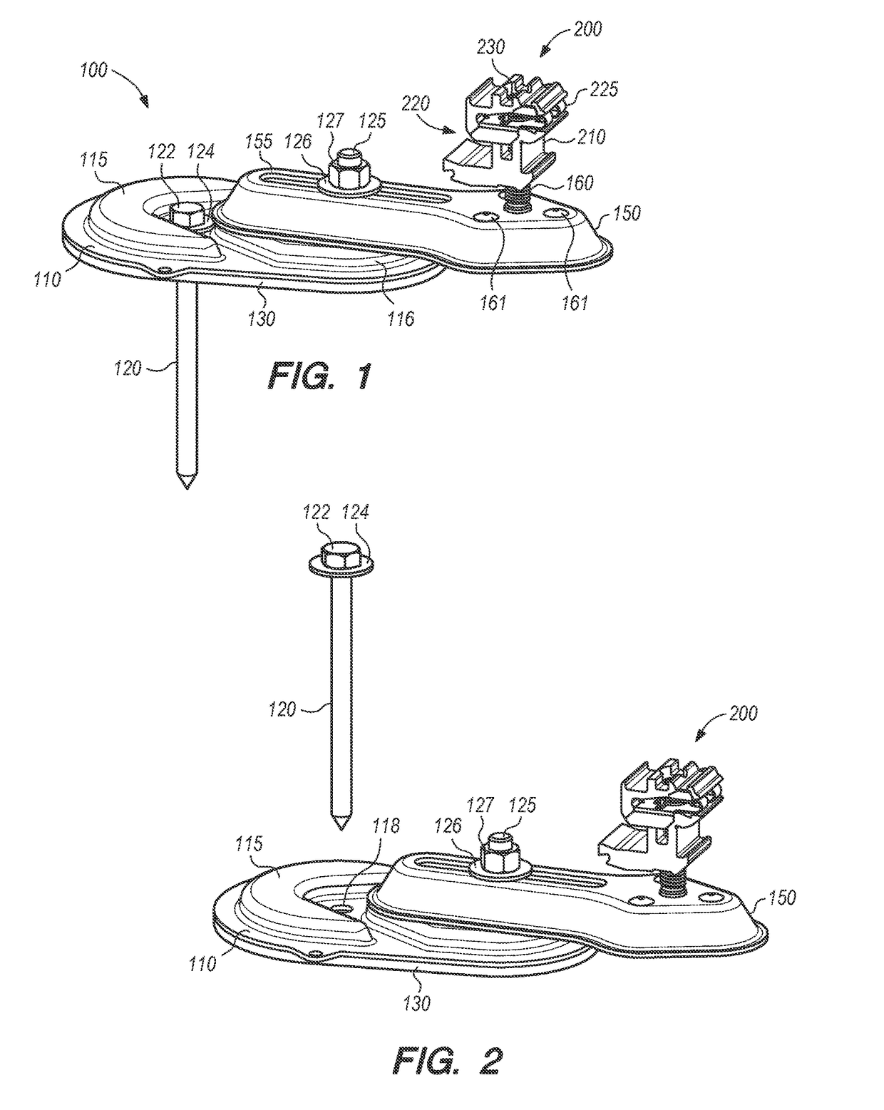
[0040]Various exemplary embodiments of the invention will now be described in greater detail in the context of the drawing figures. Referring now to FIG. 1, this Figure illustrates a perspective view of a two-piece photovoltaic module mounting system according to various embodiments of the invention. System 100 includes base portion 110 and movable portion 150. Base portion 110 is adapted to rest on a roof surface of a structure (e.g., residence, barn, garage, office, or other building) and may therefore be substantially planar in its geometry to match the substantially planer geometry of a roof surface, such as a composite shingle roof surface.

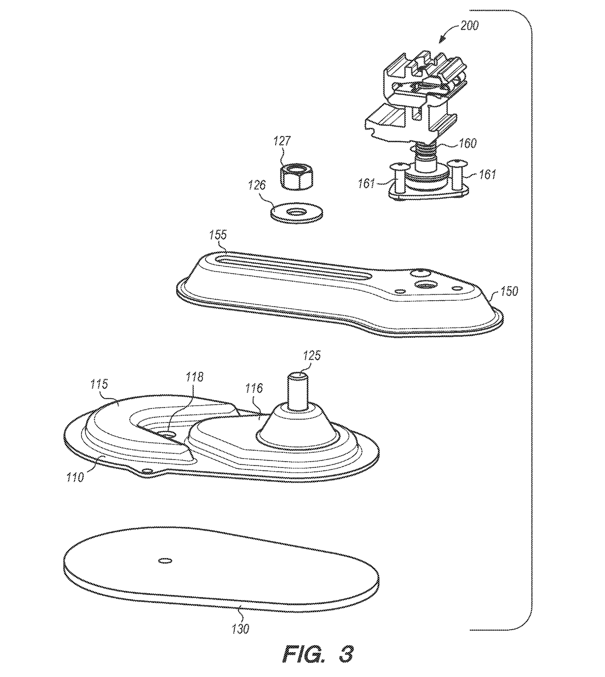
[0041]In various embodiments, and as illustrated in FIG. 1, base portion 110 may include raised portions 115 and 116 respectively that together provide a level platform for movable portion 150 to rest on as it is moved into the desired position with respect to base portion 110. Base portion 110 may also have opening 118, as shown in FIGS. 2, ...


PUM


Abstract

A two-piece rooftop photovoltaic mounting system. A fixed base portion is attached directly to a roof surface via a lag bolt or other mechanical fastener. A movable portion is attached to and pivots about the base portion providing freedom of movement radially and axially with respect to the base portion. A photovoltaic module coupler is attached to the movable portion to support at least two photovoltaic modules at a location dictated by positioning of the movable portion. A locking nut locks the movable portion to the base portion at the desired location. A sheet of sealant material under the base portion helps prevent ingress of water into the roof surface via the lag bolt.

Description

CROSS REFERENCE TO RELATED APPLICATIONS[0001]This application claims priority to provisional patent application Nos. 62 / 112,559, filed Feb. 5, 2015, and 62 / 109,659, filed Jan. 30, 2015, the disclosures of which are hereby incorporated by reference in their entirety.FIELD OF THE INVENTION[0002]The invention relates to photovoltaic energy generation mounting systems and more specifically to systems and methods for installing photovoltaic modules on composition shingle roofs.BACKGROUND OF THE INVENTION[0003]Residential and commercial solar power has become increasing popular as industry costs have come down and the importance of diversifying away from fossil fuel-based power has increased. Some of this is attributable to reductions in module costs and some is attributable to innovations in mounting hardware, which in turn reduce material costs and labor costs. Other factors, including rising CO2 levels, and increased awareness of climate change are also contributing to the rapid adopti...

Claims


Application Information

Patent Timeline
Patent Type & Authority Patents(United States)
IPC IPC(8): H02S20/00H02S20/30H02S20/23
CPCH02S20/30H02S20/23F24J2/52Y02B10/12F24S25/61F24S25/636F24S25/65Y02B10/10Y02B10/20Y02E10/47Y02E10/50F24S25/00
Inventor ALMY, CHARLESHUDSON, TYRUSMOLINA, DAVIDWEST, JACK
Owner TESLA INC
Why Eureka
Try Eureka