Inductively coupled wireless power and data for a garment via a dongle

a technology of inductive coupling and dongle, which is applied in the direction of transmission, electrical equipment, circuit arrangements, etc., can solve the problems of affecting the function of the device, preventing the proper alignment of the primary and secondary coils, and exposing the system to man-made contaminants, so as to reduce the stray magnetic field, and low the effect of the level

Active Publication Date: 2018-03-06
CYNETIC DESIGNS
View PDF14 Cites 17 Cited by
  • Summary
  • Abstract
  • Description
  • Claims
  • Application Information

AI Technical Summary

Benefits of technology

[0008]The invention described herein an inductive wireless power transfer system wherein a secondary inductive power coil assembly is contained within a small dongle that is in a preferred embodiment located on the end of a short umbilical cable connected to a soldier power management system in a soldier's tactical garment. The secondary coil receives wireless inductive power from a primary inductive charge unit located within a vehicle. When the soldier sits in a vehicle seat the secondary coil dongle is in one embodiment, inserted into a primary charging receptacle that is located on or immediately adjacent to the troop seat. When the dongle is placed into the wireless power receptacle, it is recognised by the primary circuit and power is transferred to the soldier system without the need of any electro-mechanical sockets or connectors. As there are no electro-mechanical connections to be made or broken, little to no dis-connect force is required to separate the connection and at any time the soldier can stand up and the dongle slides out of the receptacle. The inductive charging transformer circuit utilises closely coupled ferrite cores that inherently reduce stray magnetic field to low levels. Additionally, the primary power unit housing provides the opportunity for implementation of secondary shielding. The system may also incorporate a secure means of providing connectorless RF or NFC audio communication and data streams across distances of less than 2 cm provide a high efficiency design with low possibility of magnetic field emissions and, when used for wireless communication and data transmission, the antennas are sufficiently close and shielded that cross talk between neighbouring devices will be eliminated.
[0009]While also eliminating the need for exposed electro-mechanical connections and associated failure prone cables and connectors, the dongle inductive charger system described herein provides an environmentally insensitive, that is, environmentally sealed and functioning in harsh conditions, encapsulated power transfer system that can operate in harsh weather or adverse environmental conditions such as mud, sand, dirt, ice, snow, rain. The system may be exposed to man-made contaminants such as petroleum, oil, lubricants and biological and chemical agents that may be found both outside or inside a military or other similar vehicle. Additional battlefield or war-fighting environmental requirements include the ability of the charger to withstand being fully submersed while performing inductive charging functions or being washed down. The primary charging receptacle may be designed such that dirt, fluids, and contaminants may pass through the primary charging device and not collect in the bottom of the primary charger, which over time, as the dirt or ice builds up within, would prevent proper alignment of the primary and secondary coils and impede the function of the device. Further implementations of the vest dongle charger system allows the charger to be used in barracks or other non-mobile applications.
[0012]To the knowledge of the applicant, a primary objective of current US Soldier modernisation programme research is to examine the potential for increasing the ruggedness, decreasing the cost and or weight of the system by improving the electrical connectors and cable / connector assemblies in future equipment ensembles.
[0016]The primary inductive driver circuit can be configured to accommodate any type of input power including both AC and DC power inputs. Typical military aircraft and vehicle power input requirements would be 28 VDC, whereas many commercial vehicles would be 12 VDC. Interface may also be required to a CANBUS system or Common Modular Power System (CMPS) smart vehicle system for easy configuration and diagnostic capability.
[0018]At the present time it is expected that initial power output to the battery charging circuit to be approximately 50 W which would allow the charging of one 100 W battery at a 0.5 C charge rate. However in the foreseeable future, the charge rate capacity of soldier system main power batteries will increase to as much as 2 C or greater. As it will be very desirable to charge the main batteries as quickly as possible to obtain as much power in what may be very short time periods, the output of the primary device will need to be in the order of 100 W or greater. If charging power requirements are reduced, then the charger provides lower amounts of power as required or may even be turned off.

Problems solved by technology

The system may be exposed to man-made contaminants such as petroleum, oil, lubricants and biological and chemical agents that may be found both outside or inside a military or other similar vehicle.
The primary charging receptacle may be designed such that dirt, fluids, and contaminants may pass through the primary charging device and not collect in the bottom of the primary charger, which over time, as the dirt or ice builds up within, would prevent proper alignment of the primary and secondary coils and impede the function of the device.
The need to charge batteries of electronic equipment on a modernised solider when the soldier is away from base support has been recognised as a significant logistic problem since the original concept of the soldier modernisation programmes.

Method used


Image

  • Inductively coupled wireless power and data for a garment via a dongle
  • Inductively coupled wireless power and data for a garment via a dongle
  • Inductively coupled wireless power and data for a garment via a dongle

Examples


Embodiment Construction

Overview of Dongle Charger

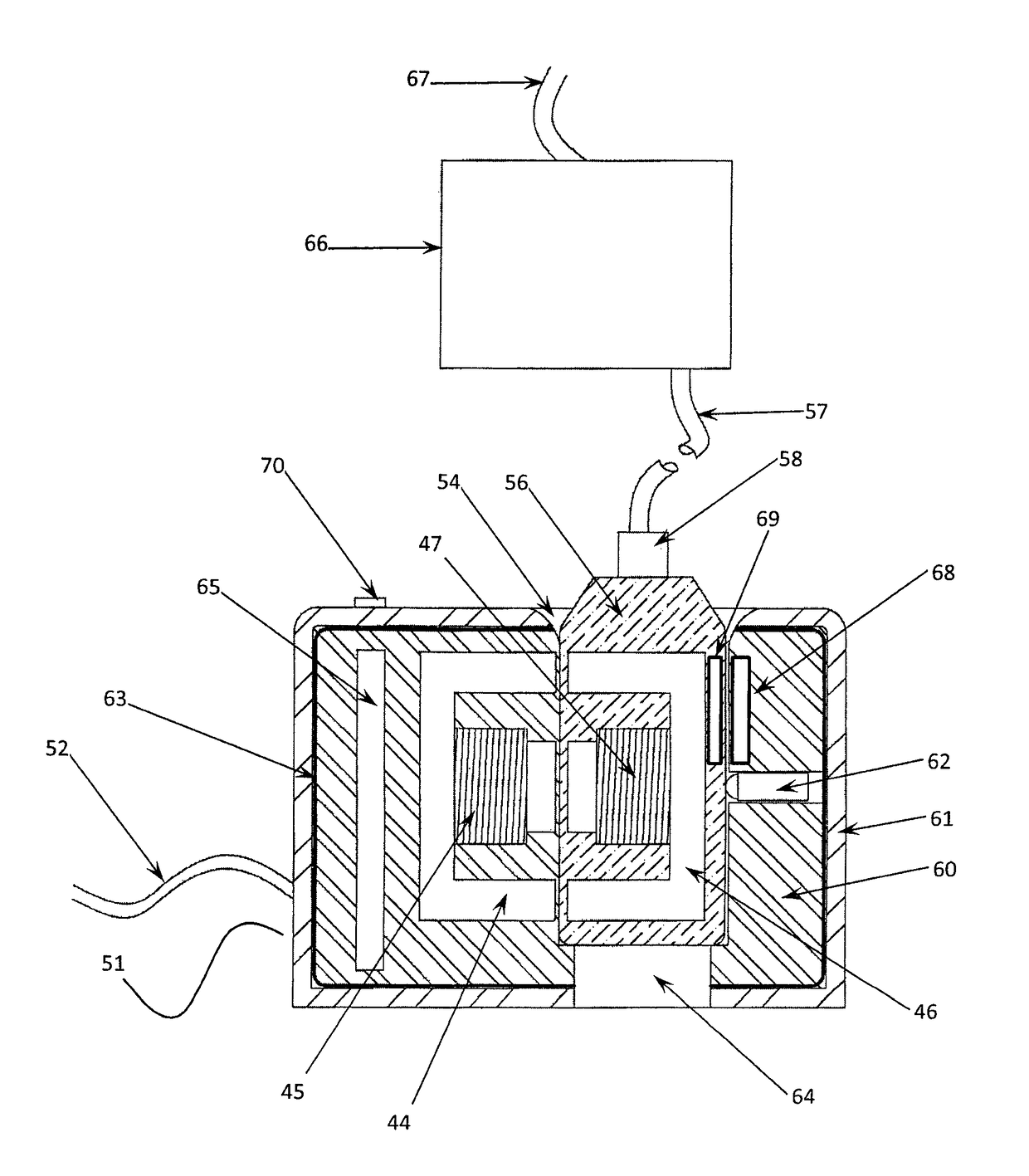
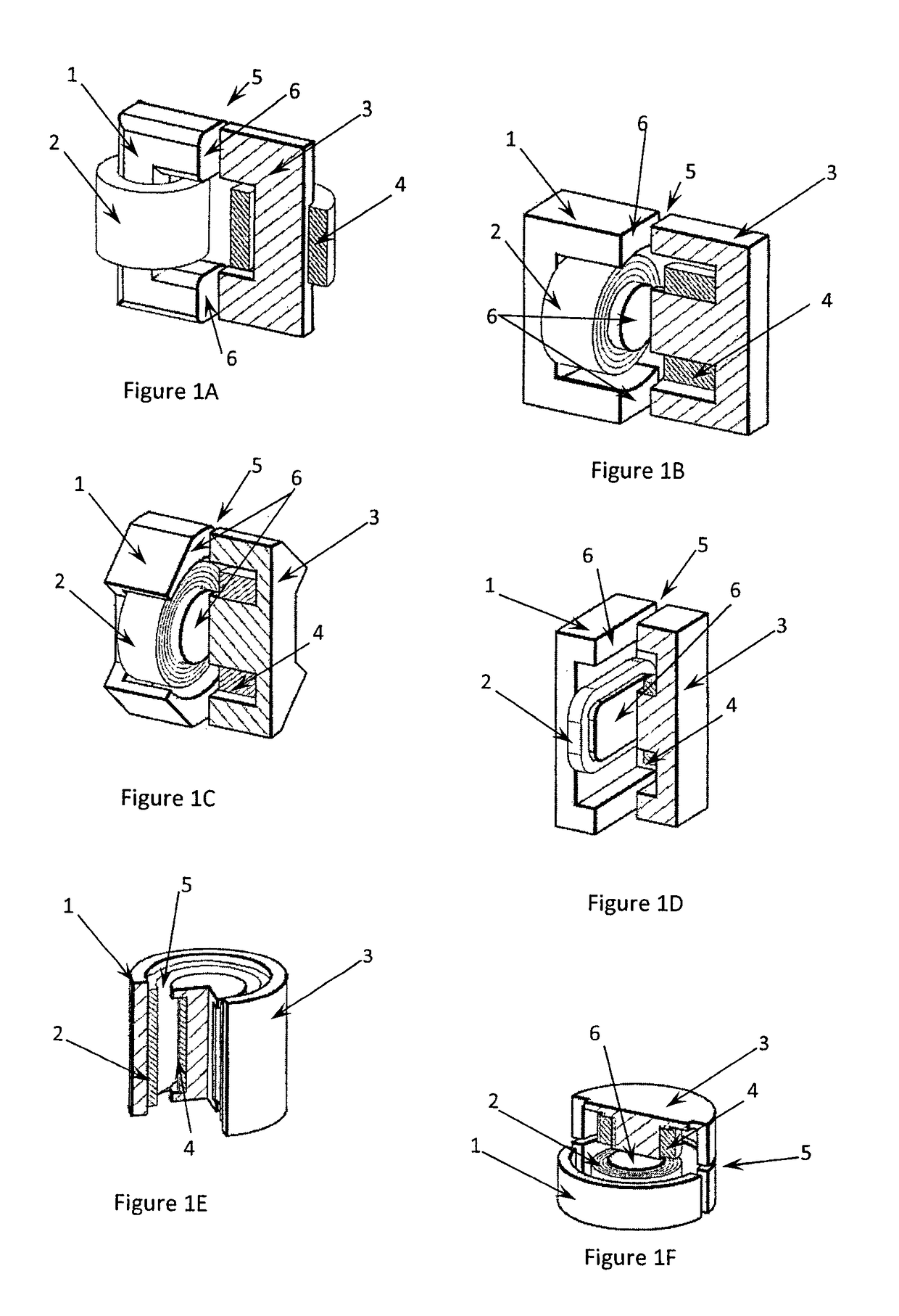
[0044]The present invention is an inductive wireless charging system that utilises two separable power ferrite core halves (FIGS. 1A-1F) that form an inductive air core transformer. The system is described as a charger as that is its usual function to provide power to charge a central battery carried by the soldier or user. The system may however be viewed simply as a power transfer system or as a data transfer system, or combination of these. A primary charging unit is attached to a vehicle seat or other support structure and receives electrical power from the vehicle. It contains an inductive power circuit that drives a primary inductive winding that is positioned on a ferrite power core. In one embodiment the ferrite core is located directly adjacent to a receptacle within the primary charging housing such that the pole or poles (legs) or pot of the ferrite core (herein collectively referred to as the ferrite core) align and allow the formation of a subs...


PUM


Abstract

A system for transmission of at least power using inductive wireless coupling includes an environmentally sealed dongle and a mounting component which releasably mates with the dongle. The dongle is sized for use with one hand, and may be coupled by an umbilical to either a garment of the user or to a vehicle structure for example a seat, in which case the mounting component is coupled to the vehicle structure or to the garment respectively. The dongle and the mounting component include first and second inductive coils respectively and corresponding ferrite cores. The coils are positioned within the dongle and mounting component so that they are aligned for their inductive coupling when the dongle and mounting component are mated. The positioning and alignment of the coils provides a substantially closed magnetic path between the coils. The mounting component may be a receptacle.

Description

FIELD OF THE INVENTION[0001]This invention relates to the field of devices using inductive coupling to transmit power and data, and in particular to a method and system for inductively coupled wireless transmission of power, or power and data, via dongle and a mounting component coupled between a garment and a structure of a vehicle.BACKGROUND[0002]Many patented applications of inductive charging now specifically reference the wireless or inductive charging of mobile electronic devices in both indoor environments and also within vehicles so as to remove the clutter and need for various charging cables that interface to the different devices. Inductive coupling frequently uses the application of charging pads, cradles or holders that incorporate mechanical, magnetic or printed means of providing or indicating alignment of the primary and secondary inductive coils to enable and obtain optimal transfer efficiencies between the primary transmit circuit and the receiving secondary circui...

Claims


Application Information

Patent Timeline
Patent Type & Authority Patents(United States)
IPC IPC(8): H02J5/00H04B5/00
CPCH02J50/12H02J50/90H02J50/70H04B5/0031H04B5/0037H04B5/0081H02J5/005H02J50/10H02J50/005
Inventor SOAR, ROGER J
Owner CYNETIC DESIGNS
Why Eureka
Try Eureka