
Seatback flexible slip plane joint for side air bag deployment

a flexible slip plane and seatback technology, applied in vehicle components, pedestrian/occupant safety arrangements, vehicle arrangements, etc., can solve the problems of airbag upholstery material torn, inconsistent airbag deployment, and substantial damage to the seatback, and achieve the effect of easy manufacturing

Active Publication Date: 2018-03-13
FORD GLOBAL TECH LLC
View PDF216 Cites 3 Cited by
  • Summary
  • Abstract
  • Description
  • Claims
  • Application Information

AI Technical Summary

Benefits of technology

The design provides a robust, easy-to-manufacture seating structure with an improved interface for airbag deployment, reducing damage to the seatback and ensuring consistent airbag deployment, while also allowing for weight reduction and enhanced passenger space.

Problems solved by technology

Typically, these side airbags are encased within the fabric upholstery material of the seatback, such that upon deployment of the airbag the upholstery material is torn.
This form of deployment may result in inconsistent airbag deployment and substantial damage to the seatback.

Method used


Image

  • Seatback flexible slip plane joint for side air bag deployment
  • Seatback flexible slip plane joint for side air bag deployment
  • Seatback flexible slip plane joint for side air bag deployment

Examples


Embodiment Construction

[0028]For purposes of description herein, the terms “upper,”“lower,”“right,”“left,”“rear,”“front,”“vertical,”“horizontal,” and derivatives thereof shall relate to the disclosure as oriented in FIG. 1. However, it is to be understood that the disclosure may assume various alternative orientations, except where expressly specified to the contrary. It is also to be understood that the specific devices and processes illustrated in the attached drawings, and described in the following specification are simply exemplary embodiments of the inventive concepts defined in the appended claims. Hence, specific dimensions and other physical characteristics relating to the embodiments disclosed herein are not to be considered as limiting, unless the claims expressly state otherwise.

[0029]In this document, relational terms, such as first and second, top and bottom, and the like, are used solely to distinguish one entity or action from another entity or action, without necessarily requiring or impl...


PUM


Abstract

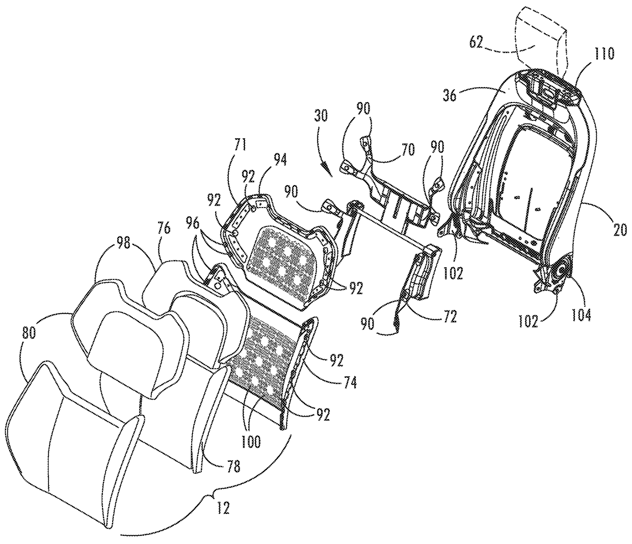
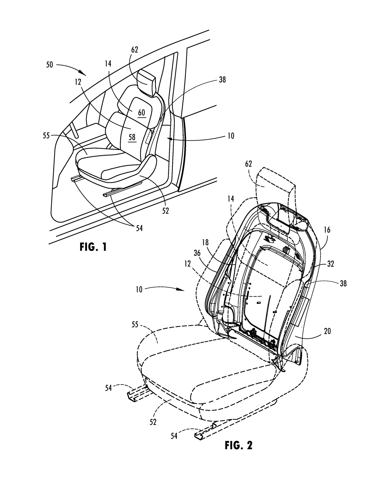
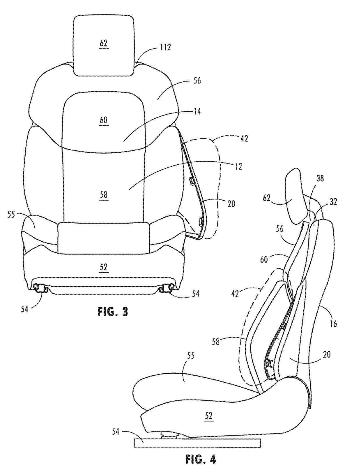
A vehicle seatback assembly includes a cushion assembly having a seating surface. A back panel includes a first side portion, a second side portion, and a back portion. A first living hinge is disposed between the first side portion and back portion. A second living hinge is disposed between the second side portion and back portion. A frame is disposed between the back panel and the cushion assembly. A peripheral cushion structure supports a periphery of the cushion assembly. A closeout panel is coupled with the back panel and is disposed behind the cushion structure to define a peripheral gap between the closeout panel and the cushion structure that extends around the sides of said seatback assembly. A shingled portion of the closeout panel extends behind and couples with the back panel. An airbag is coupled with the frame and is configured to deploy between the closeout and back panels.

Description

FIELD OF THE DISCLOSURE[0001]The present disclosure generally relates to a vehicle seatback assembly, and more particularly to a seatback flexible slip plane joint for side air bag deployment for a vehicle seatback assembly.BACKGROUND OF THE DISCLOSURE[0002]It is becoming increasingly more common for vehicles to include airbag assemblies in locations that allow the contained airbag to deploy to desired areas of protection quickly and with a high degree of precision. It is generally understood that one location airbag assemblies are more frequently incorporated is within a seatback for deploying between a passenger and an adjacent vehicle door. Typically, these side airbags are encased within the fabric upholstery material of the seatback, such that upon deployment of the airbag the upholstery material is torn. This form of deployment may result in inconsistent airbag deployment and substantial damage to the seatback. As vehicle seats are equipped with airbag assemblies, it is also b...

Claims


Application Information

Patent Timeline
Patent Type & Authority Patents(United States)
IPC IPC(8): B60R21/207B60R21/2155B60R21/231B60R21/215
CPCB60R21/207B60R21/231B60R21/2155B60R21/215B60N2/686B60N2/6009B60N2/64
Inventor LINE, JOHNATHAN ANDREWKONDRAD, MARCOS SILVASOYKA, JR., RICHARD JOSEPHCARR, LISA MARIEBILLARDELLO, NICHOLAS ALPHONSE
Owner FORD GLOBAL TECH LLC
Learn More