Method for determining an antenna array

a technology of antenna array and antenna array, which is applied in the direction of antennas, instruments, measurement devices, etc., can solve the problems of increasing the size of the antenna array and the limitation of the maximum directivity level which may be achieved with this type of antenna array structure, so as to improve the directivity and reduce the compactness

Active Publication Date: 2018-03-13
COMMISSARIAT A LENERGIE ATOMIQUE ET AUX ENERGIES ALTERNATIVES
View PDF12 Cites 10 Cited by
  • Summary
  • Abstract
  • Description
  • Claims
  • Application Information

AI Technical Summary

Benefits of technology

[0009]Therefore there exists a need for a method for determining an antenna array with which it is possible to obtain an antenna array having improved directivity with reduced compactness.
[0010]According to the invention, this object is achieved with a method for determining an antenna array able to generate an electromagnetic wave, comprising at least one antenna and at least one circuit having parameters which have an influence on the electromagnetic wave generated by the antenna array and connected to at least one antenna. The method comprises steps for selecting a criterion to be met for the wave generated by the antenna array and for determining desired decomposition coefficients of a wave in a basis with which the selected criterion may be attained. The method also comprises a step for calculating parameters having an influence on the electromagnetic wave generated by the antenna array for each circuit of the antenna array so that the difference between the decomposition coefficients on the basis of the wave generated by the antenna array and the desired decomposition coefficients be minimal.

Problems solved by technology

However, these solutions strongly increase the size of the antenna array.
However, the maximum directivity level which may be attained with this type of antenna array structure is limited by the directivity of the ideal Huygens source, which is of 4.7 dBi.

Method used


Image

  • Method for determining an antenna array
  • Method for determining an antenna array
  • Method for determining an antenna array

Examples


Embodiment Construction

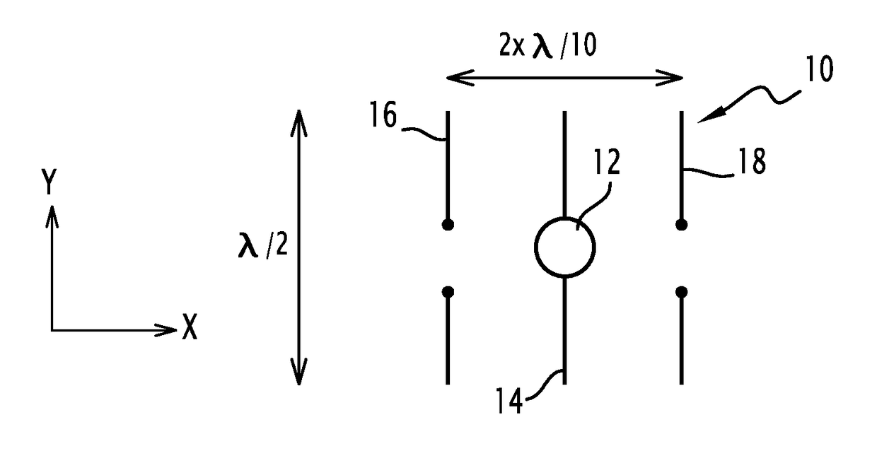
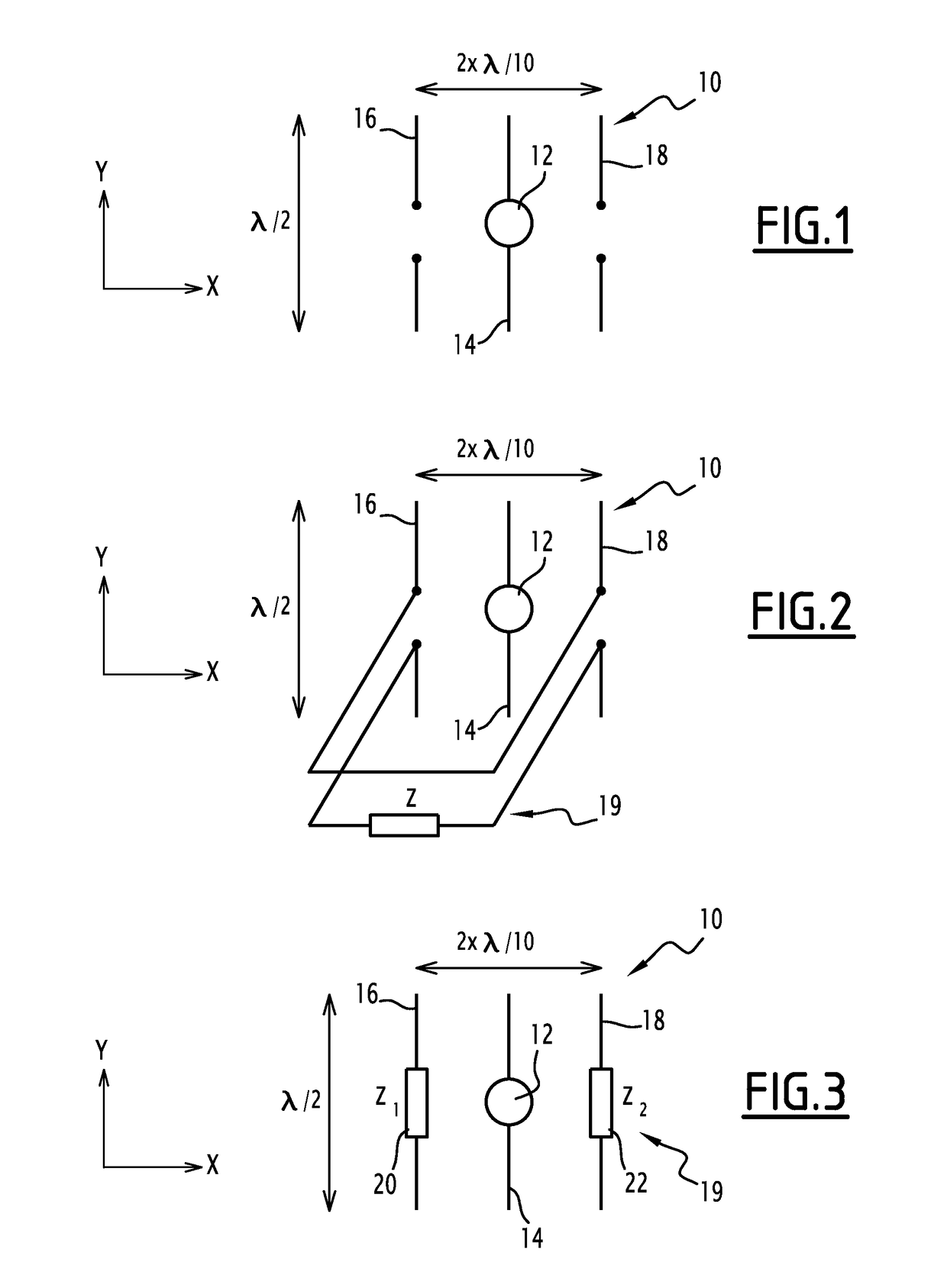
[0025]An antenna array 10 is proposed, as illustrated in a generic way in FIG. 1 and by both embodiments of FIGS. 2 and 3. An antenna array generally comprises of at least one primary antenna and one secondary antenna. Each of these antennas being part of the antenna array comprises one or several radiating portions. The radiating portions of each separate antenna are physically separate. By the expression “physically separate”, it is meant that there is no physical contact between two radiating portions belonging to two separate antennas.

[0026]For what follows, two axes X and Y contained in FIGS. 1 to 3 are defined. The axis X is perpendicular to the axis Y. A direction parallel to the X axis is called a longitudinal direction and a direction parallel to the axis Y is called a transverse direction.

[0027]The antenna array 10 includes a source 12, a first antenna 14, a second antenna 16, a third antenna 18 and a circuit 19 (not shown in FIG. 1).

[0028]The first antenna 14 is an antenn...


PUM


Abstract

A method for generating an electromagnetic wave with an antenna array, the antenna array including at least one antenna, at least one circuit having parameters having an influence on the electromagnetic wave generated by the antenna array and connected to at least one antenna, and the method comprising: selecting a criterion to be met for the wave generated by the antenna array; determining desired decomposition coefficients of a wave in a basis giving the possibility of attaining the selected criterion; and calculating the parameters having an influence on the electromagnetic wave generated by the antenna array for each circuit of the antenna array so that the difference between the decomposition coefficients on the basis of the wave generated by the antenna array and the desired decomposition coefficients be minimal.

Description

FIELD OF THE INVENTION[0001]The present invention relates to a method for determining an antenna array. The present invention also relates to an antenna array.BACKGROUND OF THE INVENTION[0002]The invention applies to the field of antenna arrays. For many applications, directive radiation is desired. As an illustration, detection and communication with a target require radiation to be focused in a preferential direction. Avoiding electromagnetic pollution outside useful areas is another example of an application involving relatively directive radiation.[0003]In order to increase the directivity of an antenna array, the use of reflectors such as parabolic antennas, the arraying of antennas and the association of coupled antennas like for antennas of the Yagi-Uda type are known from the state of the art.[0004]However, these solutions strongly increase the size of the antenna array. Indeed, the directivity of a reflective antenna is estimated conventionally by the formula[0005]D=4⁢πλ2⁢A...

Claims


Application Information

Patent Timeline
Patent Type & Authority Patents(United States)
IPC IPC(8): G01S1/00H01Q23/00H01Q19/30H01Q5/385
CPCH01Q23/00H01Q19/30H01Q5/385
Inventor BELMKADDEM, KAWTARRUDANT, LIONEL
Owner COMMISSARIAT A LENERGIE ATOMIQUE ET AUX ENERGIES ALTERNATIVES
Why Eureka
Try Eureka