Laparoscopic radiofrequency surgical device

a radiofrequency surgical and laparoscopic technology, applied in the field of electrosurgical systems and methods, can solve the problems of particularly challenging jaw alignment in the mutual field, and achieve the effect of preventing or correcting incipient lateral slippage and preventing lateral slippag

Active Publication Date: 2018-03-20
AESCULAP AG
View PDF596 Cites 210 Cited by
  • Summary
  • Abstract
  • Description
  • Claims
  • Application Information

AI Technical Summary

Benefits of technology

[0010]Embodiments of the jaws may be rotatable with respect to each other by way of a pinless rotation mechanism that operates by way of rotatably cooperative features of the jaws that connect the jaws together. The pinless rotatable mechanism, in addition to securing the jaws together, allows the jaws to pivot between the open position and the closed position. Embodiments of the jaw set may pivot as a whole between an open and a closed position by virtue of one jaw pivoting with respect to a shaft while the other jaw remains fixed with respect to the shaft. The center of rotation of this pinless rotation system is not necessarily disposed at a position on a line corresponding to a central longitudinal axis of the shaft. Particular embodiments of the pinless rotation mechanism are displaced from that line. An advantage of this pivotal or rotational mechanism is that force that is transferred to the mechanism from an actuator wire is increased by the angular moment provided by the distance of displacement of the center of rotation from the longitudinal axis of the shaft, or more particularly by the distance between the axis of the actuator wire within the shaft and the center of rotation.
[0021]Some embodiments of an electrosurgical device include a blade that is capable of separating radiofrequency-sealed tissue into two portions. Embodiments of the blade maybe be positioned on a longitudinally disposed blade track; the blade may be positioned at home position at a proximal end of the track, at a distal end of the track, or at any point along the track between the distal and proximal ends of the track. In various embodiments of the device, when the jaws are in the open position, the proximal home position of the blade is configured such that the movement of the blade in a distal direction is prevented. In some embodiments, distal movement may be physically blocked by an impeding structure distal to the blade, in other embodiments distal movement may be prevented by a locking mechanism proximal to the blade.
[0027]As summarized above, some embodiments of the set jaws are configured in a manner such that the jaws self align with respect to their longitudinal axes when the jaws are approaching closure. Accordingly, in these jaw set embodiments, the tissue-engaging surfaces of each of the opposing jaws, respectively, have mutually complementary longitudinally oriented self-aligning features that prevent lateral slippage of jaws as they close toward each other. Inasmuch as these features prevent or correct incipient lateral slippage as the jaws close, these features may be characterized as longitudinally aligning and laterally stabilizing aspects of the tissue-engaging surfaces.
[0028]Embodiments of self-aligning jaw features may be disposed along the substantial entirety of the length of the jaws. In another aspect, embodiments of self-aligning jaw features may as occupy the substantial entirety of available tissue engaging surfaces of the jaws. In various embodiments, the self-aligning features may fully or substantially occupy the length tissue-engaging surfaces of the jaws; in other embodiments, the self-aligning features may occupy only a portion of the length of tissue-engaging surfaces of the jaws. The structural features associated with this approach to longitudinally aligning the jaws generally conserves on materials, costs, or dimensions, that would otherwise be associated with achieving manufacturing tolerances required to support a guarantee of collinear alignment of the two jaws when they close.
[0048]In some embodiments of the method, moving the set of jaws into a proximity of the target tissue further includes rotating the jaws around their central longitudinal axis. Rotating the jaws may occur by way of rotating the shaft of the device around its central longitudinal axis. Rotating the shaft of the device may occur by rotating a shaft rotation actuator proximal to the shaft. In various embodiments of the method, embodiments of the shaft rotation actuator, the shaft, and the jaws may all have the capability of rotating freely in both clockwise and counter clockwise directions without a stop, or a need to reverse direction.

Problems solved by technology

The mutual alignment of the jaws can be particularly challenged when the jaws are closing around a piece of tissue, whose presence can urge the jaws to skew laterally out of alignment such that they do not meet opposingly.

Method used


Image

  • Laparoscopic radiofrequency surgical device
  • Laparoscopic radiofrequency surgical device
  • Laparoscopic radiofrequency surgical device

Examples


Embodiment Construction

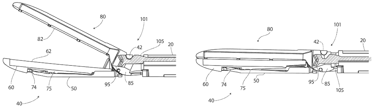
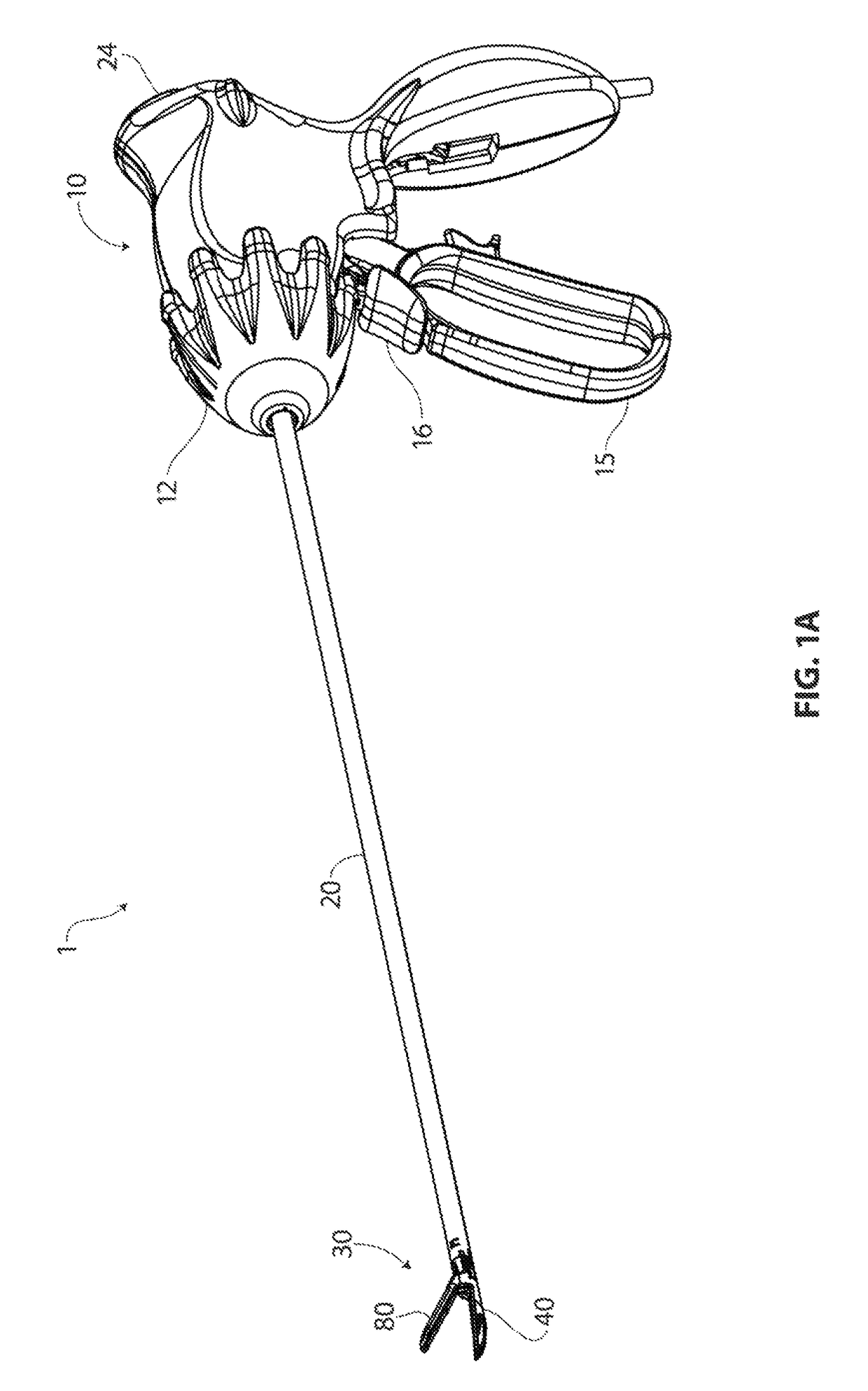
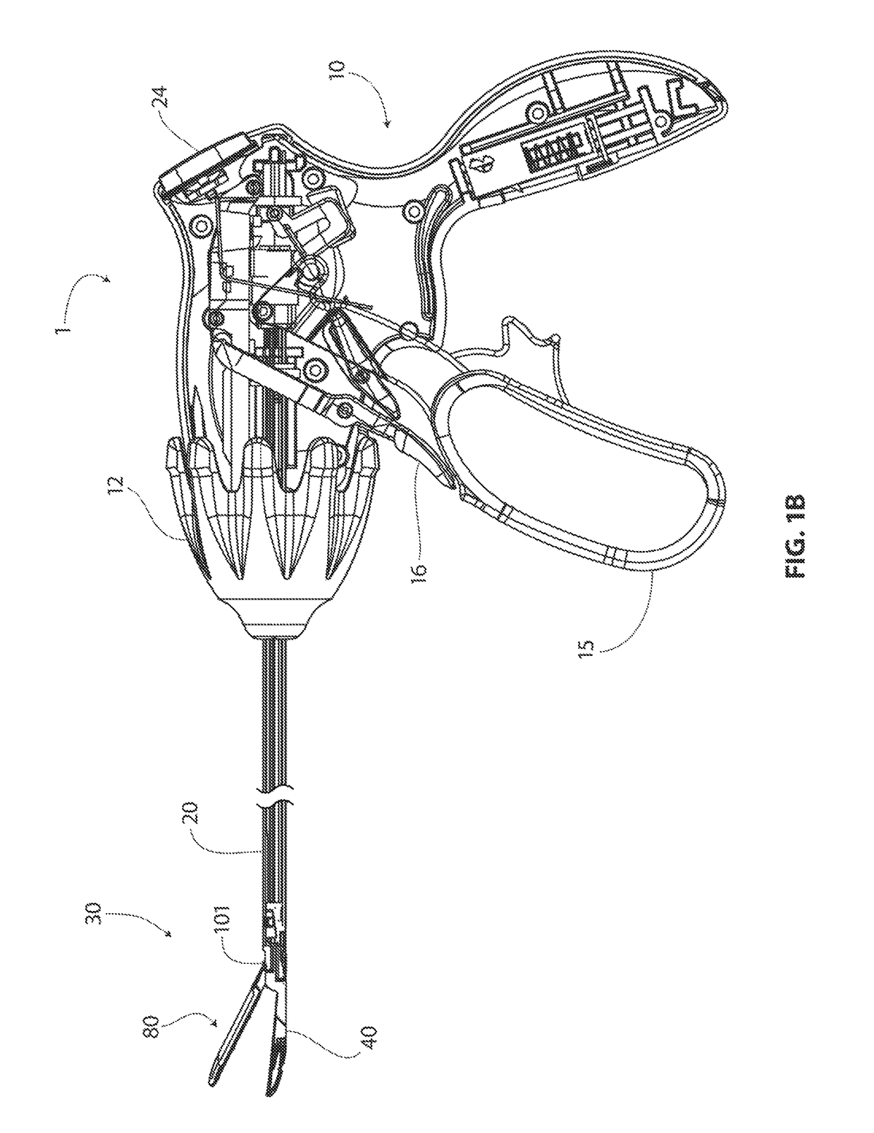
[0109]Embodiments of the technology described herein provide various improvements over available electrosurgical devices, such improvements permitting a physical downsizing of a device to a dimension that permits practical use of an electrosurgical device within the constraints of a laparoscopic surgical environment. One of these constraints to working laparoscopically relates to the 5 mm inner diameter opening provided by a commercially standard trocar. A device compatible with the 5 mm opening constraint needs to have an insertable configuration with a maximal diameter that is insertable therethrough. These technological improvements are generally directed toward creating a high degree of efficiency with regard to performance of the device per unit volume or cross sectional area. For example, a jaw set of a disclosed device, in spite of small physical dimension, is able to deliver an appropriate level of force to tissue being clamped by the jaws, and the structure and material of ...


PUM


Abstract

Embodiments of the disclosed technology relate to a bipolar electrosurgical device for a laparoscopic environment, as well as methods for the use of such a device. Embodiments of the device may include a set of opposing jaws comprising at least one bipolar electrode pair disposed thereon, the set of jaws configured to deliver radiofrequency energy to a target tissue. Embodiments of the set of jaws, when closed, may have a diameter no greater than about 5 mm. The device may further include a shaft with a diameter that may be no greater than about 5 mm. Each of the jaws has a tissue-facing surface of each jaw that may include a complementary self-aligning configuration with respect to the longitudinal axis of the other jaw. Embodiments of the device may further include a pinless rotation assembly formed from rotatably cooperative features of the first jaw and the second jaw that connect the jaws together and enable the jaw set to pivot between an open position and a closed position.

Description

CROSS-REFERENCE TO RELATED APPLICATIONS[0001]This application claims priority to U.S. Provisional Patent Application No. 61 / 301,295 of Walberg, entitled “Laparoscopic RF Surgical Device”, as filed on Feb. 4, 2010, now lapsed. This application is also a continuation-in-part of U.S. patent application Ser. No. 11 / 743,579 of Eder et al., entitled “Surgical Tool”, as filed on May 2, 2007, now U.S. Pat. No. 8,574,229, which issued Nov. 5, 2013, that application being a continuation-in-part of U.S. patent application Ser. No. 11 / 382,652, of Eder et al., entitled “Apparatus for Tissue Cauterization”, as filed May 10, 2006, now U.S. Pat. No. 7,942,874, which issued May 17, 2011, and claiming priority to U.S. Provisional Patent Application No. 60 / 746,256 of Eder et al., entitled “Surgical Tool”, as filed on May 2, 2006, now lapsed.INCORPORATION BY REFERENCE[0002]All publications and patent applications mentioned in this specification are herein incorporated by reference to the same extent as...

Claims


Application Information

Patent Timeline
Patent Type & Authority Patents(United States)
IPC IPC(8): A61B18/14A61B17/29A61B18/00A61B90/00
CPCA61B18/1445A61B2090/064A61B2018/0063A61B2018/00505A61B2018/00589A61B2018/00595A61B2018/00601A61B2018/00678A61B2018/00702A61B2018/00791A61B2018/00827A61B2018/00875A61B2018/1412A61B2018/1455A61B2017/2932
Inventor WALBERG, ERIKLOUDERMILK, BRANDON
Owner AESCULAP AG
Why Eureka
Try Eureka