Motor drive control device

a control device and motor technology, applied in computer control, instruments, etc., can solve problems such as noise generation of gear rattling, and achieve the effects of increasing the rotation speed, and reducing the rotation speed of the motor

Active Publication Date: 2018-03-20
TOYOTA JIDOSHA KK
View PDF4 Cites 2 Cited by
  • Summary
  • Abstract
  • Description
  • Claims
  • Application Information

AI Technical Summary

Benefits of technology

[0006]The present invention has been made to solve the problem described above, and therefore has an object to prevent a speed reducer from being increased in size and / or the number of components from being increased so as to reduce gear rattling noise generated in the speed reducer.
[0031]In the motor drive control device for controlling the driving of the motor in accordance with the target torque, even when the direction of the target torque is reversed, the torque generated by the motor is required to quickly follow the target torque. In response to the request described above, according to one embodiment of the present invention, the magnitude of the braking torque and the magnitude of the driving torque in the first direction, which are to be generated during the idling time period, are set to the same value. Therefore, a large torque can be generated within the range of capability of the motor in both the first time period in which the relative velocity (approach velocity) of the tooth of the input-side gear to the tooth of the output-side gear and the second time period in which the relative velocity (approach velocity) of the tooth of the input-side gear to the tooth of the output-side gear during the idling time period. Therefore, according to one embodiment of the present invention, the reduction of gear rattling noise generated in the speed reducer and followability of the motor torque can be both achieved.

Problems solved by technology

In the in-wheel motor driven automobile, when a direction of a torque of each of the motors is reversed, there is a fear in that gear rattling noise may be generated due to a backlash in the speed reducer and be audible to a driver.

Method used


Image

  • Motor drive control device
  • Motor drive control device
  • Motor drive control device

Examples


Embodiment Construction

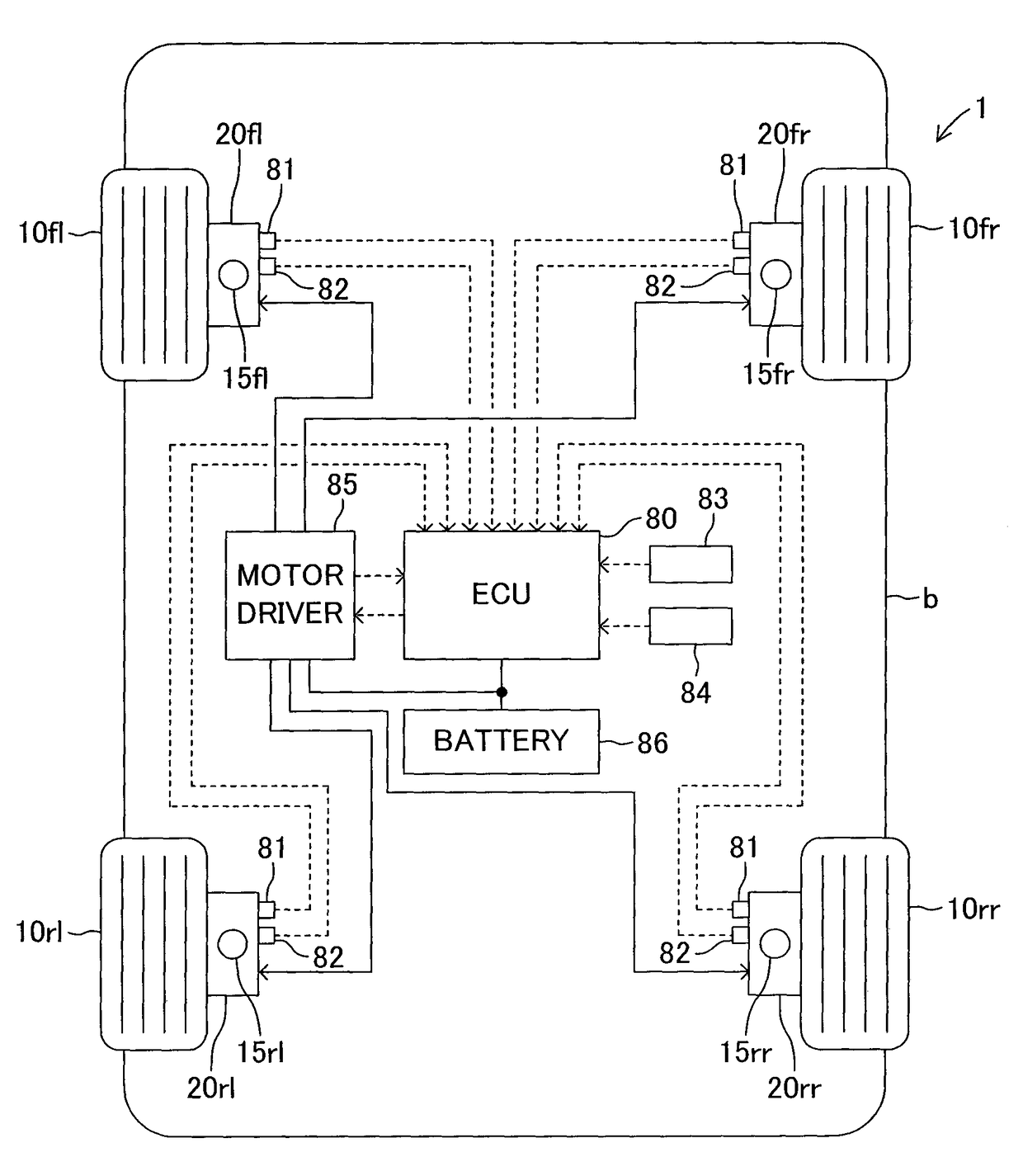
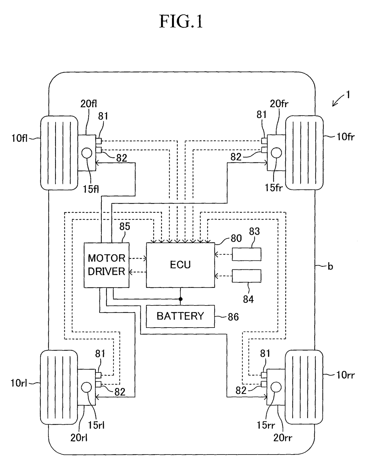
[0042]A description is now given of a motor control device according to an embodiment of the present invention. FIG. 1 schematically illustrates a configuration of an in-wheel motor driven vehicle on which a motor drive control device according to this embodiment is mounted.

[0043]A vehicle 1 includes a front left wheel 10fl, a front right wheel 10fr, a rear left wheel 10rl, and a rear right wheel 10rr. In-wheel motor units 20fl, 20fr, 20rl, and 20rr are incorporated into the inside of the front left wheel 10fl, the front right wheel 10fr, the rear left wheel 10rl, and the rear right wheel 10rr, respectively. The in-wheel motor units 20fl, 20fr, 20rl, and 20rr are supported to a vehicle body b respectively by suspensions 15fl, 15fr, 15rl, and 15rr. Hereinafter, the front left wheel 10fl, the front right wheel 10fr, the rear left wheel 10rl, and the rear right wheel 10rr are simply referred to as “wheels 10” unless any one thereof is required to be specified. Similarly, the in-wheel m...


PUM


Abstract

A motor drive control device is capable of reducing gear rattling noise generated in a speed reducer without increasing size of the speed reducer and the number of components. A motor ECU controls a motor to generate a reverse set torque (Tn) when a target torque (T*) is reversed (at a time t1). The motor ECU sequentially calculates a backlash (B) in a counter gear mechanism, and sets a time period (D1) in which the reverse set torque (Tn) is generated by the motor and a time period (D2) in which a return set torque (Tp) is generated by the motor so that the backlash (B) at a current time becomes equal to a time integrated value (corresponding to an area A) of an estimated relative velocity (V2−V1) until a time of re-abutment.

Description

TECHNICAL FIELD[0001]The present invention relates to a motor drive control device to be mounted in an in-wheel motor driven automobile.BACKGROUND ART[0002]There is hitherto known an in-wheel motor driven automobile including motors and speed reducers that are arranged inside of wheels. In the in-wheel motor driven automobile, when a direction of a torque of each of the motors is reversed, there is a fear in that gear rattling noise may be generated due to a backlash in the speed reducer and be audible to a driver. Patent Literature 1 proposes a technology of reducing the gear rattling noise generated due to the backlash in the speed reducer. An in-wheel motor provided with a speed reducer, which is proposed in Patent Literature 1, includes a motor output shaft to be fitted into a rotor, which is divided into two portions. To each of the two portions of the motor output shaft, an output section including a speed reducer is coupled. One of the output sections includes a first helical...

Claims


Application Information

Patent Timeline
Patent Type & Authority Patents(United States)
IPC IPC(8): B60K6/365B60L11/18G05B15/02B60K1/04B60K17/356B60K17/04B60K7/00B60W10/08B60L15/20B60L3/00B60L15/38F16H15/28B60K6/26
CPCB60L15/38B60K6/365B60K7/0007B60K17/043B60K17/046B60K17/356B60L3/0023B60L11/18B60L15/20B60L15/2009B60L15/2054B60W10/08G05B15/02B60K1/04Y02T10/7275B60K2007/0038B60K2007/0061B60L2240/421B60L2240/423B60L2240/48B60L2260/26B60L2270/14B60L2270/142B60W2710/083Y02T10/645Y02T10/72B60L50/60Y02T10/64Y02T10/70
Inventor TERADA, MAKITOFUKUDOME, HIDEKI
Owner TOYOTA JIDOSHA KK
Why Eureka
Try Eureka