
Target object for a laser measuring device and method for identifying the target object

a laser measuring device and target object technology, applied in the direction of active open surveying means, instruments, surveying and navigation, etc., can solve the problems of not being able to identify and differentiate between the target objects, and achieve the effect of preferably low equipment expenditures in the laser measuring device for identifying the target obj

Active Publication Date: 2018-03-20
HILTI AG
View PDF18 Cites 1 Cited by
  • Summary
  • Abstract
  • Description
  • Claims
  • Application Information

AI Technical Summary

Benefits of technology

This patent is about a laser measuring device that has a target object that can be easily identified and distinguished from other objects using visible transmission beams that have different colors. This is helpful for the user who is using the device. The device uses monochrome LEDs which are cost-effective and reliable. This technology also reduces the need for infrared laser beams that can reflect from surfaces and make it difficult to identify the target object. The use of differently colored visible transmission beams helps to identify more target objects and also allows for easier differentiation between them.

Problems solved by technology

The target objects have the disadvantage that it is not possible to identify and to differentiate between the target objects.
It is disadvantageous that the laser measuring device and the target object must be connected via a communication link in order to identify the target object.

Method used


Image

  • Target object for a laser measuring device and method for identifying the target object
  • Target object for a laser measuring device and method for identifying the target object
  • Target object for a laser measuring device and method for identifying the target object

Examples


Embodiment Construction

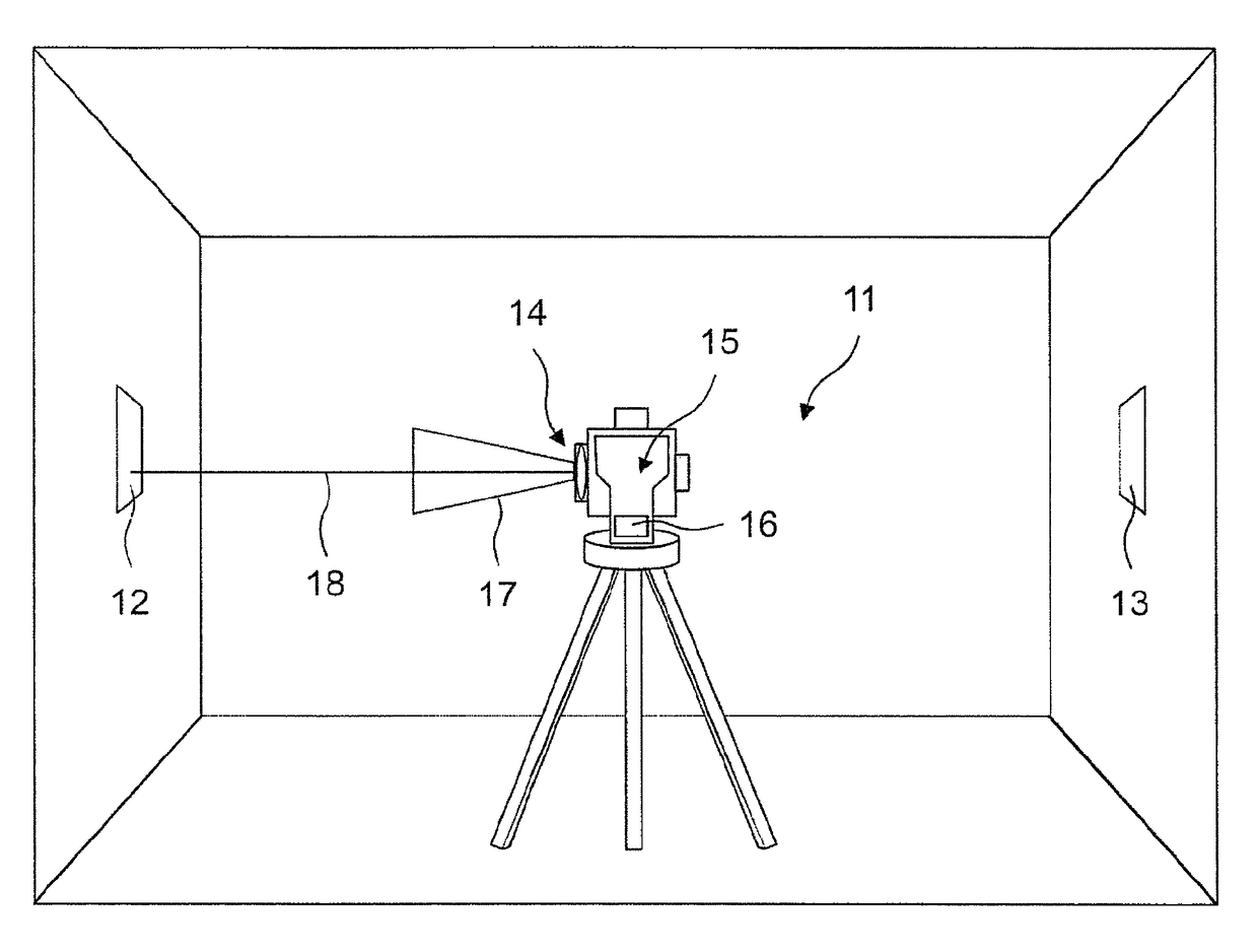
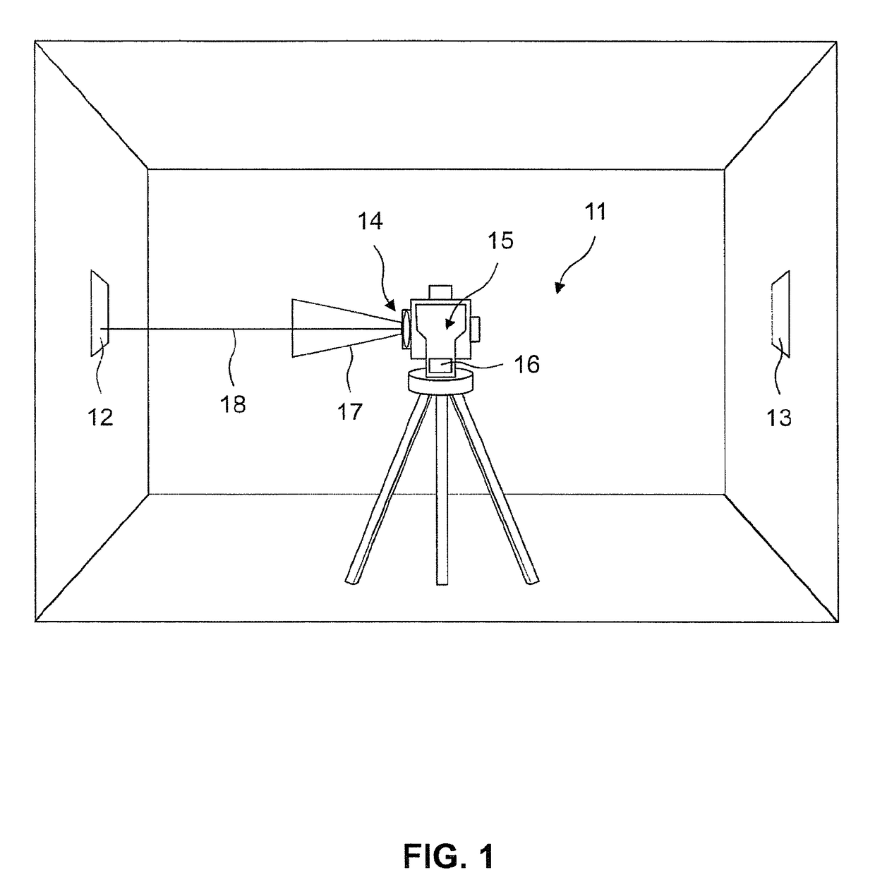
[0023]FIG. 1 shows in a schematic representation a surveying system 10 including a laser measuring device 11, a first target object 12 according to the present invention, and a second target object 13 according to the present invention. Target objects 12, 13 are situated in a measurement environment, in the example of FIG. 1 at two opposite walls of a room. In addition to being fastened on the walls or ceilings of a room, target objects 12, 13 may be fastened on a tripod or a telescopic pole.

[0024]Laser measuring device 11 includes a laser measuring unit 14, a camera unit 15 and a control device 16. Laser measuring unit 14 includes a first and a second beam source, the first beam source transmitting a search beam 17 and the second beam source transmitting a measuring beam 18. Search beam 17 is used to recognize and identify target objects in the measurement environment. In order for search beam 17 not to disturb the users and other people in the measurement environment, the search b...


PUM


Abstract

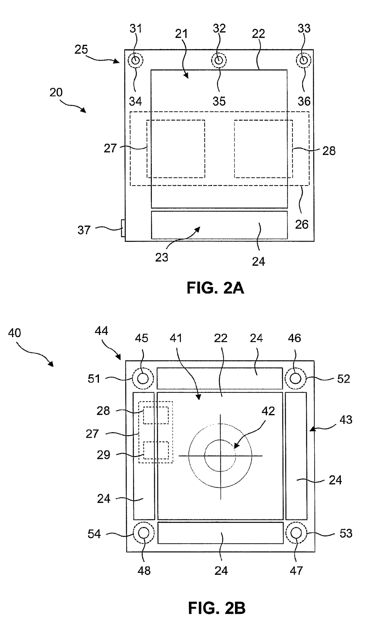
A target object (20) for a laser measuring device (11) emitting a search beam and a measurement beam, including a reflector device (21) having at least one reflector element (22) for reflecting the measurement beam, a receiving device (23) having at least one receiving element (24) for receiving the search beam, a transmitting device (25) having at least one transmitting element (31, 32, 33) for emitting a visible transmission beam (34, 35, 36) and a control device (26) having an evaluation element (27) for evaluating the received search beam and a control element (28) for controlling the receiving and transmitting devices (23, 25) is provided. The transmitting device (25) emits a first and a second visible transmission beam (34, 35), wherein the color of light of the first visible transmission beam (34) differs from the color of light of the second visible transmission beam (35).

Description

[0001]The present invention relates to a target object for a laser measuring device as well as a method for identifying the target object with the aid of the laser measuring device.BACKGROUND[0002]Laser measuring devices are used for measuring target points which determine distances and directions (angles) of the target points. Laser measuring devices are known which are designed as a theodolite, a total station, a dumpy level, or a laser scanner. The laser measuring devices include a distance measuring device for measuring the distance between the target point and the distance measuring device and an angle measuring device for measuring angles. The measurement of the target points is supported by target objects which are placed at the target points. The target objects are used in surveying systems including laser measuring devices which transmit a search beam and a measuring beam, the wavelengths for the search beam and the measuring beam being advantageously different. The measuri...

Claims


Application Information

Patent Timeline
Patent Type & Authority Patents(United States)
IPC IPC(8): G01C3/08G01C15/00
CPCG01C15/006G01C15/002G01C15/06
Inventor WINTER, ANDREAS
Owner HILTI AG
Learn More