Switch wire connection device

a technology of switch wire and connection device, which is applied in the direction of contact electric connection, electrical apparatus, connection, etc., can solve the problems of increased manufacturing cost, unbeneficial increase of the volume of the case, and difficulty for the operator to aim the tool at the screw, etc., to achieve enhanced stability of operation, simple structure, and easy operation

Active Publication Date: 2018-03-20
SWITCHLAB +1
View PDF5 Cites 3 Cited by
  • Summary
  • Abstract
  • Description
  • Claims
  • Application Information

AI Technical Summary

Benefits of technology

[0011]It is therefore a primary object of the present invention to provide an improved switch wire connection device, which has a simplified structure and is easy to operate with enhanced stability of operation. The switch wire connection device includes a conductive component mounted in an insulation case, a switch pushbutton assembled with the conductive component and an electrical contact. The electrical contact has a restriction unit and a contact plate connected with the restriction unit. By means of operating the pushbutton, the conductive component is driven to selectively electrically contact or separate from the contact plate. The restriction unit is divided into a first space and a second space, in which a first leg section and a second leg section of a metal leaf spring are respectively assembled. The wiring circuits or conductive wires of a machine or equipment can be easily directly plugged into the first and second spaces of the restriction unit and held by the first and second leg sections of the metal leaf spring. In addition, during the operation process, the metal leaf spring is prevented from deflecting.
[0013]In the above switch wire connection device, the first side is bent toward the third side and extends to form a first subsidiary side. The fourth side is bent toward the second side and extends to form a fifth side. The fifth side and the first side are positioned on the same plane. The fifth side is bent toward the third side and extends to form a second subsidiary side. The first and second subsidiary sides are side by side arranged in parallel to each other to divide the restriction unit into a first space and a second space for respectively receiving the first and second leg sections of the metal leaf spring. At least the second side and the first subsidiary side serve to help in restricting the moving path of the first leg section of the metal leaf spring and the fourth side and the second subsidiary side serve to help in restricting the moving path of the second leg section of the metal leaf spring. The contact plate has a first end and a second end. The first end is connected with the first and fifth sides of the restriction unit. The second end is an inclined and lifted structure and extends in a direction to contact the conductive component.
[0014]In the above switch wire connection device, the first subsidiary side is formed with a first raised section directed to the second subsidiary side. The second subsidiary side is formed with a second raised section directed to the first subsidiary side. The first and second raised sections serve to compensate the gap between the first and second subsidiary sides, whereby when operating and moving the metal leaf spring, the first and second raised sections together prevent the first and second subsidiary sides from over-deflecting or over-swing. Accordingly, the moving path of the metal leaf spring can be truly restricted.

Problems solved by technology

Under such circumstance, it is troublesome and hard for the operator to aim the tool at the screw to drive the screw for locking the conductive wire with the electrical contact (or termed electrical connection terminal).
Such structure is relatively complicated so that the manufacturing cost is increased and generally the volume of the case is enlarged to avoid interference between the guide structures and the conductive component.
The increase of the volume of the case is unbeneficial to the miniaturization of the switch wire connection terminal device and fails to meet the trend to miniaturize the switch wire connection terminal device.
Also, in some operation environments (such as the operation of the machine or the equipment will cause vibration), after a long term of use, the screw is apt to loosen.
As a result, the conductive wire may loosen and detach from the case.
Especially, when driving the screw mechanism to lock the conductive wires with the electrical contact, it is necessary to use a tool for tightening / untightening the screw.
Such process is relatively troublesome.
The manufacturing process of the α-shaped metal leaf spring is quite troublesome and complicated.
In the conventional switch wire connection device, it is hard and troublesome for an operator to aim the tool at the screw to drive the screw for locking the conductive wire with the electrical contact.
In addition, it is troublesome to assemble the guide channels and guide ribs of the insulation case and the electrical contact and the spring.
Also, an α-shaped metal leaf spring is applied to the insulation case and the structure of the switch wire connection device is complicated.

Method used


Image

  • Switch wire connection device
  • Switch wire connection device
  • Switch wire connection device

Examples


Embodiment Construction

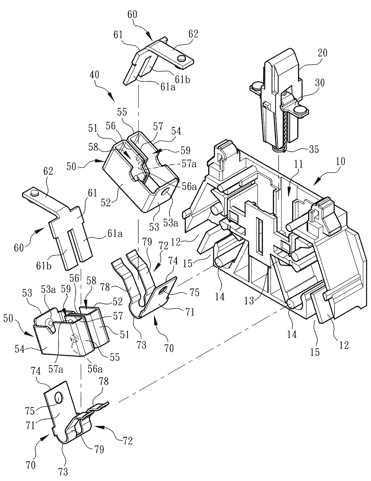
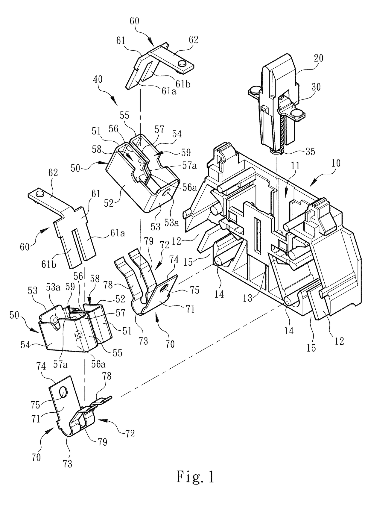
[0024]Please refer to FIGS. 1 and 3. The switch wire connection device of the present invention includes an insulation case 10 and a switch pushbutton 20 assembled with the insulation case 10. The case 10 has a cavity 11 for receiving the switch pushbutton 20. The switch pushbutton 20 is assembled with a conductive component 30 and a spring 35. (This pertains to prior art and thus will not be further described hereinafter). According to the direction of FIG. 1, the lower end sections of two sides of the case 10 are formed with wire sockets 12 in communication with the cavity 11. The wiring circuits or conductive wires 90 of an electronic or an electrical apparatus can be plugged through the wire sockets 12 into the cavity 11 to connect with the electrical contact 40.

[0025]Basically, according to the practical application form, the switch wire connection device of the present invention permits at least two conductive wires 90 to side by side plug into the case 10 and connect with the...


PUM


Abstract

A switch wire connection device has a simplified structure and is easy to operate with enhanced stability of operation. The switch wire connection device includes a conductive component mounted in an insulation case, a switch pushbutton assembled with the conductive component and an electrical contact. The electrical contact has a restriction unit and a contact plate connected with the restriction unit. By means of operating the pushbutton, the conductive component is driven to selectively electrically contact or separate from the contact plate. The restriction unit is divided into a first space and a second space, in which a first leg section and a second leg section of a metal leaf spring are respectively assembled. The wiring circuits or conductive wires can be easily directly plugged into the first and second spaces of the restriction unit and held by the first and second leg sections.

Description

BACKGROUND OF THE INVENTION[0001]1. Field of the Invention[0002]The present invention relates generally to an improved switch wire connection device, and more particularly to a switch wire connection device including a restriction unit, a contact plate and a metal leaf spring assembled with each other for directly electrically connecting with a conductive wire. The restriction unit has higher rigidity and is able to help in fixing the metal leaf spring and restricting the moving path thereof.[0003]2. Description of the Related Art[0004]A conventional switch wire connection device is a power switch device capable of connecting circuits or conductive wires. The switch wire connection device is installed on an operation panel or distribution box of an electronic or electrical apparatus for connecting the wiring circuits. The switch wire connection device has an insulation case (generally made of plastic material) and a conductive component enclosed in the insulation case and a screw fo...

Claims


Application Information

Patent Timeline
Patent Type & Authority Patents(United States)
IPC IPC(8): H01H13/14H01H1/58H01H13/50H01H13/04
CPCH01H1/58H01H13/50H01H13/04H01R9/2433H01R4/48275
Inventor WU, CHIH-YUANWU, CHERNG SHIN
Owner SWITCHLAB
Why Eureka
Try Eureka