Surgical robot system

a robot and robot technology, applied in the field of surgical robot systems, can solve the problems of patient body, inability to access information on the wider operating environment, movement of auxiliary theatre staff, etc., and require considerable for

Active Publication Date: 2018-03-27
ABB (SCHWEIZ) AG
View PDF12 Cites 149 Cited by
  • Summary
  • Abstract
  • Description
  • Claims
  • Application Information

AI Technical Summary

Benefits of technology

[0005]One object of the present invention is to create a surgical robot system with which the danger of undesired contacts between the robotic arm or an instrument guided by the robotic arm and the patient can be minimized.

Problems solved by technology

However, one problem with such operations is that, although the operating surgeon can observe the immediate surgical field by means of the camera and control a surgical instrument held by the robot, information on the wider operating environment, on movements of the auxiliary theatre staff who are present etc. is not accessible through direct sensory impressions.
However, if the operating surgeon is not precisely aware of the shape of the robotic arm guiding the tool and its possible movements, in extreme cases this can lead to undesired contacts between the robotic arm and the patient's body and can in extreme cases lead to injuries.
In the case of orthopedic operations in particular, such assisting activities frequently require the exertion of considerable force, which can exceed the capacities of human assistants but which, in contrast, a robot can apply for an indefinite period without tiring or diminishing in its precision.
The aforementioned limitation of the execution of the control commands can in particular consist in that if the current location of the robotic arm lies within the specified movement space, but the target location of a control command lies outside of this, the path of the robotic arm from the current location to the target location is calculated, a point on this path is determined at which the robotic arm reaches the boundary of the movement space, and the second control instance passes on a modified control command to the robotic arm, the target location of which is this point, so that the movement of the robotic arm ends on reaching the boundary.
In other words, the locking mechanism cannot be opened and the patient support cannot be detached from the substructure as long as the robotic arm is in a movement space suitable for performing an operation.
The fact that the robotic arm is prevented in this way from coming into contact with the patient's body does not prevent work from being carried out, since a tool held by the robotic arm for this purpose can project from the movement space of the robotic arm.

Method used


Image

  • Surgical robot system
  • Surgical robot system
  • Surgical robot system

Examples


first embodiment

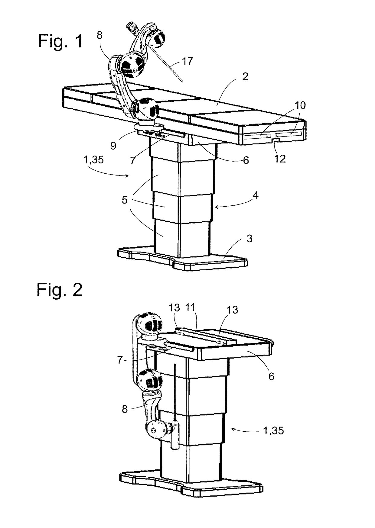
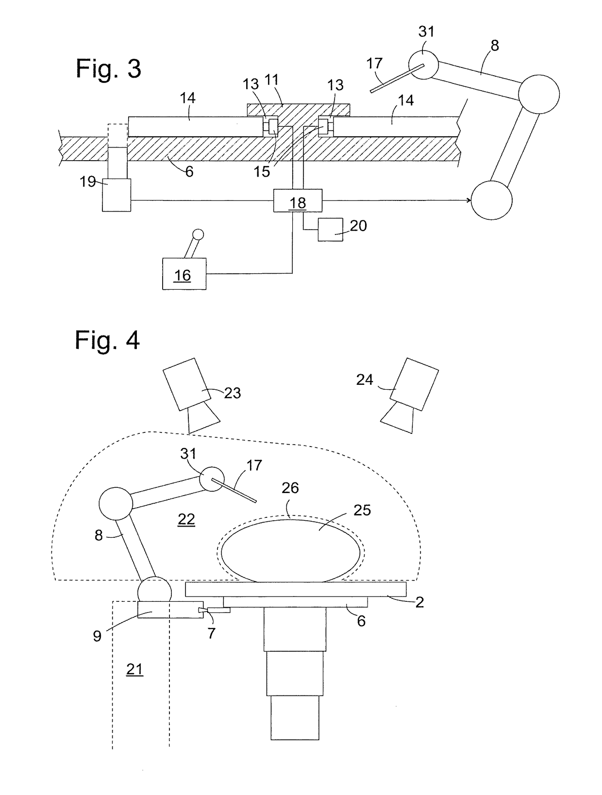
[0033]FIG. 1 shows the robot system according to the invention in a perspective view. A base element 1, in this case designed as a pedestal base 35, and a patient support 2 mounted detachably on the base 35 form an operating table. In this case the base 35 comprises a base plate 3 mounted firmly on, for example bolted to, the floor, and a column 4 which in this case is composed of a plurality of telescopically interlocking, height-adjustable segments 5. The upper end of the base 35 is formed by a support plate 6 which supports the patient support 2 and which carries on its longitudinal edge a rail 7, to which a robotic arm 8 is detachably attached. In this case a foot section 9 of the robotic arm 8 comprises two clamping jaws which can be moved relative to one another and which can be clamped onto the rail 7 with the aid of quick-release levers. The quick-release levers make it possible for the robotic arm 8 to be attached to and removed from the base 35 quickly and placed in differ...

second embodiment

[0042] the execution instance 16 also comprises an input instrument which can be moved in several degrees of freedom and a processor; however, the functional principle of the processor is different: when the input instrument is in an idle position, the processor does not generate any control commands; if the input instrument is deflected from the idle position, it generates control commands in order to move the robotic arm 8 in a direction specified through the direction of the deflection with a speed proportionate to the extent of the deflection.

third embodiment

[0043] the execution instance 16 comprises a microphone and a computer-supported speech recognition system which allows it to respond to spoken instructions by a surgeon and so gives the latter the possibility of controlling the robotic arm 4 while simultaneously using his hands to work on the patient himself.

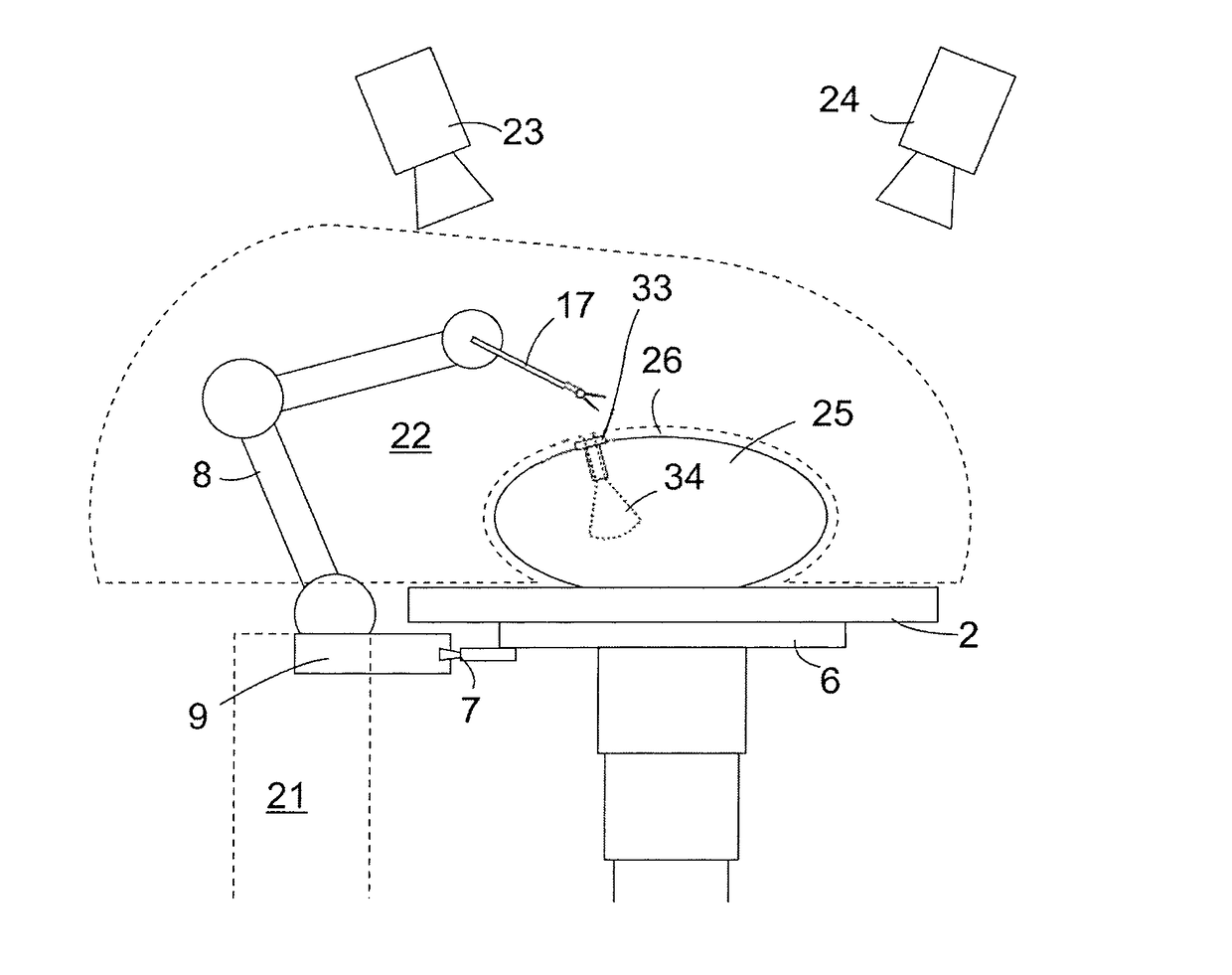
[0044]In particular if—as in the case of the first and second embodiment—it can be manually controlled, the execution instance 16 can be positioned physically separate from the other parts of the surgical robot systems. This makes it possible for the surgeon to carry out the operation at a distance from the patient. Even a surgeon who is not physically present in the operating theatre is thus given the possibility of working on the patient with the aid of the robotic arm 8. A camera which supplies this surgeon with the necessary feedback regarding the current position of an instrument 17 held by the robotic arm 8 can be firmly mounted in the operating theatre, for example on it...


PUM


Abstract

The invention relates to a surgical robot system comprising a robot arm (8) installed on a substructure (1), a first control instance (16) for producing control commands for the robot arm (8) on the basis of user inputs, and a second control instance (18), which receives the control commands from the first control instance (16) and checks the control commands with respect to whether the execution of the control commands by the robot arm (8) requires the robot arm to leave a specified occupied space (21, 22) of the robot arm (8) and releases a control command for execution by the robot arm (8) at most to the extent to which the control command can be executed without the robot arm leaving the specified occupied space (21, 22, 30).

Description

TECHNICAL FIELD[0001]The present invention relates to a surgical robot system for surgical, in particular minimally-invasive, applications. Robots have been widely used in industrial production for many years and make it possible to rationalize production thanks to their ability to reproduce pre-programmed working sequence very quickly and as often as required.BACKGROUND INFORMATION[0002]Only relatively recently have robotic applications also become of public interest in the field of surgery. In the case of surgical robots, the objective is not the exact repetition of programmed working sequences, since the movements which need to be performed are not repeated from one operation to the next. Unlike industrial robots, surgical robots are not therefore controlled by a fixed program; their movements are defined in each individual case by a surgeon controlling the robot who, whether with the naked eye or with the aid of a camera, observes the robot and its surgical field. In order to op...

Claims


Application Information

Patent Timeline
Patent Type & Authority Patents(United States)
IPC IPC(8): A61B34/30B25J9/16A61B17/00A61B90/00
CPCA61B34/30B25J9/1666A61B90/03G05B2219/45117A61B2017/00119A61B2017/00477A61B2090/0808A61B90/361
Inventor GOMBERT, BERNDKRAUSEN, LEOPOLD
Owner ABB (SCHWEIZ) AG
Why Eureka
Try Eureka