Vehicle braking unit and method

a technology of brake system and hydraulic brake, which is applied in the direction of brake control system, brake system, vehicle components, etc., can solve the problems of inability to activate the brake pressure build-up, for example for traction control or electronic stabilization of the vehicle, and the space requirement of the brake fluid pump and the pressure vessel is disadvantageously larg

Inactive Publication Date: 2018-03-27
WABCO GMBH
View PDF23 Cites 1 Cited by
  • Summary
  • Abstract
  • Description
  • Claims
  • Application Information

AI Technical Summary

Benefits of technology

[0009]Generally speaking, it is an object of the present invention to provide for an active brake pressure build-up in an improved manner.
[0017]Alternatively or in addition, by means of the built-up storage pressure, the valve device actively modulates the parking brake release pressure for the parking brake. In this way, the parking brake can be operated and released hydraulically. Here, the parking brake preferably comprises at least one spring brake cylinder, wherein the spring-type actuator engages the parking brake counter to the parking brake release pressure. A reduction of the parking brake release pressure thus leads to engagement of the parking brake, and an increase of the parking brake release pressure leads to release of the parking brake.
[0022]The shut-off valve is preferably designed such that, in the unoperated or deenergized state, it assumes its pass-through position under the force of a spring and, when operated or electrically energized, provides a shut-off action. The feed flow valve is preferably designed such that, in the deenergized state, it assumes its locking position under the force of a spring and, in the energized state, increases the respective brake pressure by means of the built-up storage pressure. In this way, the service brake can continue to be operated by means of the master brake cylinder even in the event of a defect, for example a power failure, whereby the feed flow valve and the shut-off valve cannot be operated. The valve device can have both the shut-off valve and the feed flow valve.
[0026]In another embodiment, the brake device has a common storage tank for the supply of brake fluid to the service brake by the master brake cylinder and for the supply of brake fluid to the brake fluid pump through the brake fluid inlet. In particular, the brake fluid accumulator device has, or is formed as, the storage tank. The brake fluid pump can preferably modulate both the outlet brake pressure and also the parking brake release pressure, such that, in this case, the active brake pressure build-up for the service brake, the active brake pressure build-up for the parking brake and the supply to the service brake modulator by means of the master brake cylinder are realized from the same storage tank. Thus, only one housing need be provided for the storage tank, resulting in a small space requirement, little assembly outlay, and a reduction in the risk of possible brake fluid losses owing to leaks in connecting lines, thus reducing costs. The common storage tank is advantageously arranged in the region of the master brake cylinder, and can be mounted on the master brake cylinder. In one embodiment of the braking method, it is accordingly the case that brake fluid is supplied from the common storage tank to the service brake by means of the master brake cylinder and to the brake fluid pump through the brake fluid inlet.

Problems solved by technology

A disadvantage of this brake system is that an active brake pressure build-up, for example for traction control or for electronic stabilization of the vehicle, is not possible, or is at best possible to a restricted extent with additional valves in the service brake modulator.
The second known brake system has the disadvantage that a brake fluid pump is required for each brake circuit, and, in each case, one pressure vessel connected downstream of the brake fluid pump is required for each brake circuit.
The brake fluid pumps and the pressure vessels have a disadvantageously large space requirement, and are expensive.

Method used


Image

  • Vehicle braking unit and method
  • Vehicle braking unit and method
  • Vehicle braking unit and method

Examples


Embodiment Construction

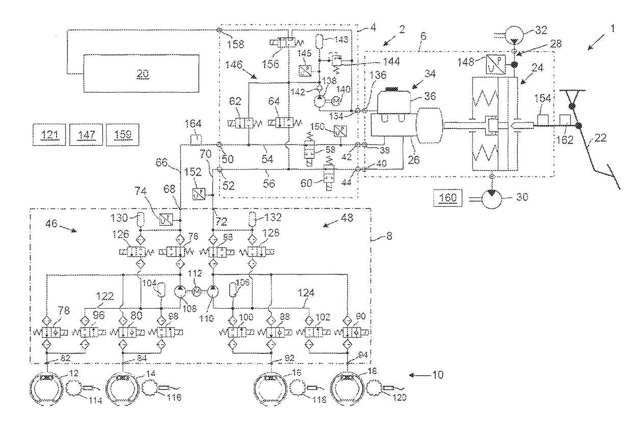
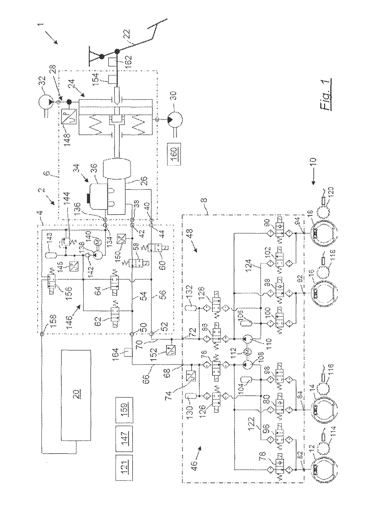
[0157]FIG. 1 shows a brake system 1 according to one exemplary embodiment of the invention. The brake system 1 has a brake device 2 that, in turn, has a brake module 4. The brake module 4 is arranged hydraulically between a servo unit 6 or a booster unit and a service brake modulator 8. The service brake modulator 8 serves to actuate a service brake 10, which has four hydraulically operable brake cylinders, specifically, a first brake cylinder 12, a second brake cylinder 14, a third brake cylinder 16, and a fourth brake cylinder 18. Furthermore, the brake module 4 directly actuates a parking brake 20, which comprises, for example, multiple spring brake cylinders. Furthermore, the brake system 1 has a brake pedal 22.

[0158]By means of the brake pedal 22, a master brake cylinder 26 is operated via a brake force booster 24. For brake force boosting, the brake force booster 24 is incorporated into a hydraulic circuit 28 in which a hydraulic pressure is provided by means of a hydraulic fl...


PUM


Abstract

A vehicle braking unit comprises an operating braking pressure inlet which receives an inlet braking pressure built up by a braking cylinder, and at least one operating brake pressure outlet at which an outlet braking pressure is provided for an operating brake modulator, which is upstream of the operating brake and provides anti-lock functionality. At least one connecting channel hydraulically connects the operating brake pressure inlet to the outlet. Brake fluid is supplied from a storage unit through the brake cylinder, the connecting channel and the operating brake modulator. The braking unit has a brake fluid inlet, through which the brake fluid is received from the storage unit, a brake fluid pump, by which the brake fluid is suctioned through the brake fluid inlet and a supply pressure is built up, and a valve unit that controls the outlet braking pressure and / or a parking brake release pressure by the supply pressure.

Description

FIELD OF THE INVENTION[0001]The invention generally relates to a braking method and brake device for the hydraulic brake system of a vehicle, in particular a utility vehicle.BACKGROUND OF THE INVENTION[0002]In hydraulic brake systems, in response to the operation of the vehicle brake pedal, pressure is generated in two service brake circuits that are filled with brake fluid, and, thus, the service brake is hydraulically operated. For this purpose, the service brake has multiple hydraulically actuable brake cylinders arranged at the axles or wheels of the vehicle. As a result of the operation of the brake pedal, the hydraulic pressure is built up in a master brake-cylinder, and is provided to the service brake circuits directly in the case of a first known brake system or via a relay valve in the case of a second known brake system. If too little brake fluid is available when the brake pedal is not actuated, brake fluid flows out of a storage tank into the master cylinder. By contras...

Claims


Application Information

Patent Timeline
Patent Type & Authority Patents(United States)
IPC IPC(8): B60T8/176B60T8/48B60T8/40B60T8/32B60T8/17B60T13/14B60T8/88
CPCB60T8/176B60T8/1708B60T8/328B60T8/4872B60T8/885B60T13/145B60T8/4072B60T2270/402
Inventor CLAUSSEN, HEIKOEICKHOFF, JURGENHEINRICH, VOLKERLULFING, RALPH-CARSTENSTRACHE, WOLFGANG
Owner WABCO GMBH
Why Eureka
Try Eureka