
Portable all-electric subsea drive module

a drive module and all-electric technology, applied in the field of subsea equipment, can solve the problems of large hydraulic equipment, such as pumps at the surface, occupying a significant amount of space on the platform or vessel, and hydraulic connections can leak hydraulic fluid into the subsea environment, so as to reduce the environmental impact of subsea operations, simplify rov tool delivery, and reduce the size and complexity of subsea tools.

Active Publication Date: 2018-03-27
ONESUBSEA IP UK LTD
View PDF13 Cites 2 Cited by
  • Summary
  • Abstract
  • Description
  • Claims
  • Application Information

AI Technical Summary

Benefits of technology

The patent text describes a new type of subsea drive module that can provide power to a tool without the need for hydraulics. This means that the tool can be powered by electricity or mechanics, which can make it a cleaner and more simple to use. It also reduces the size and complexity of the tools, making them easier to deliver using an ROV (Remotely Operated Vehicle).

Problems solved by technology

For example, hydraulic supply lines are large and expensive and hydraulic equipment, such as pumps at the surface, are large and take up a significant amount of space on the platform or vessel.
Moreover, hydraulic connections can leak hydraulic fluids into the subsea environment.
The use of hydraulic power also tends to complicate delivery subsea tool delivery.

Method used


Image

  • Portable all-electric subsea drive module
  • Portable all-electric subsea drive module
  • Portable all-electric subsea drive module

Examples


embodiment 100

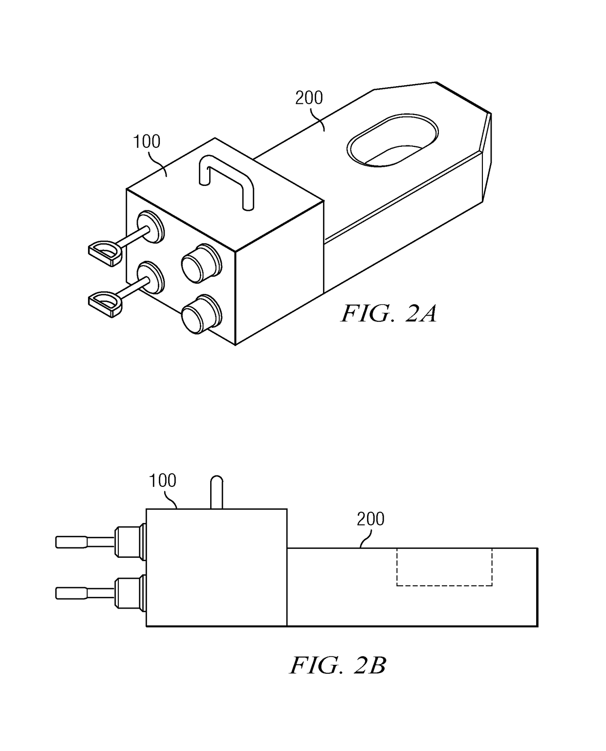
[0024]In FIG. 3B subsea drive module embodiment 100′ is similar to embodiment 100 in that it includes an electrical power supply 120 such as a lithium battery pack and an electrical motor 130 deployed in a housing 110′. The electrical motor 130 is configured to drive a magnetic coupling 160 via gearing mechanism 145. The gears 145 may be configured for example to provide increased torque to the coupling 160. Subsea drive module 100′ differs from drive module 100 (FIG. 3A) in that it includes an external magnetic coupling (external to housing 110′) that is intended to contact and magnetically lock to a corresponding magnetic coupling 260 in the subsea tool 200′. Subsea drive module 100′ may further include an ROV interface 150 (e.g., as described above with respect to FIG. 3) and an ROV handle 158 that may enable an ROV to transport the module 100′.

[0025]FIGS. 4A-4C (referred to collectively herein as FIG. 4) depict example subsea drive module embodiments 300 and 300′. The drive modu...

embodiment 300

[0027]FIG. 4C depicts a substantially vertical subsea drive module embodiment 300′ deployed in a corresponding cavity 210 in a subsea tool 200 (such as a subsea tree). Drive module embodiment 300′ includes an electrical power supply 320 that provides power to electronics module 360. The electrical power supply also provides power to electrical connectors 370 that are configured to mate with and to provide electrical power to corresponding electrical connectors 280 in subsea tool 200. In such an embodiment, the subsea drive module may provide electrical power (e.g., DC battery power) to the subsea tool 200. The electrical connectors may include substantially any suitable electrical connectors suitable for use in subsea environments such as conventional “wetable” connectors or inductive connectors. Such connectors are known in the industry and may provide a reliable connection in high pressure subsea environments. Subsea drive module 300′ may further include one or more ROV handles an...


PUM


Abstract

A subsea tool assembly includes a subsea tool and a subsea drive module connected to and configured to provide drive power to the subsea tool. The subsea drive module includes a housing configured for operation in a subsea environment, an electrical motor deployed in the housing, and an electrical power supply deployed in the housing. The electrical motor is configured to rotate a magnetic coupling which is sized and shaped to magnetically engage a corresponding magnetic coupling in the subsea tool. The electrical power supply is electrically connected to and configured to provide electrical power to the motor. Rotation of the magnetic coupling rotates the corresponding magnetic coupling in the subsea tool thereby providing drive power to the subsea tool.

Description

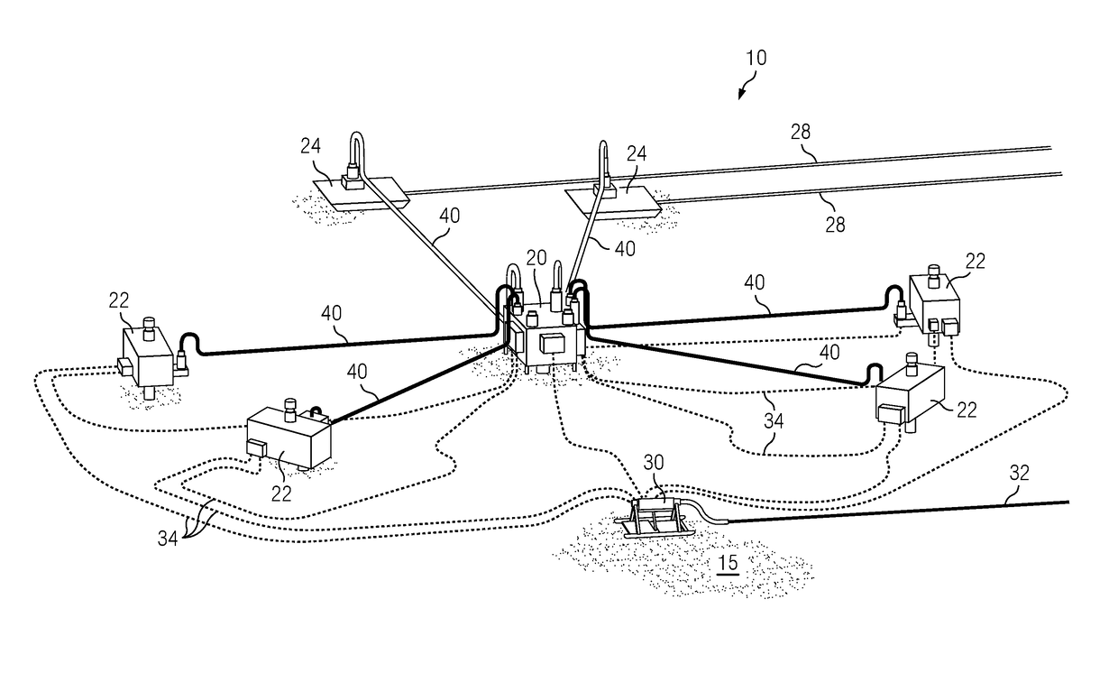
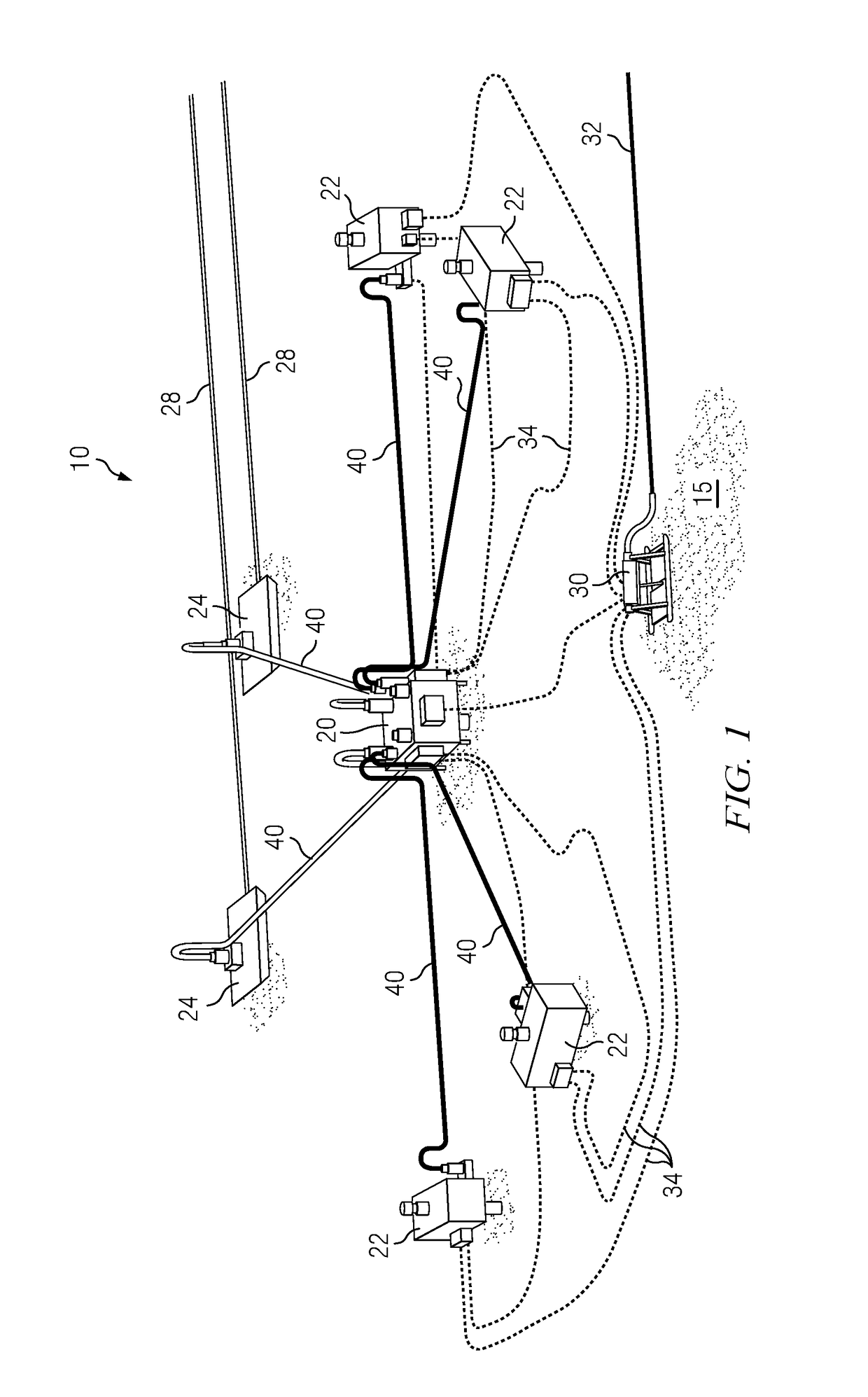
CROSS REFERENCE TO RELATED APPLICATIONS[0001]None.FIELD OF THE INVENTION[0002]Disclosed embodiments relate generally to subsea equipment and more particularly to a portable, electrically powered, subsea drive module for powering subsea equipment.BACKGROUND INFORMATION[0003]Subsea tools and production equipment commonly require a power source and drive mechanism to perform their intended function(s). Such tools and equipment generally employ hydraulic power and drive mechanisms, for example, provided by one or more hydraulic lines in communication with a subsea termination unit or other source of pressurized hydraulic fluid. While such hydraulic power and drive mechanisms are serviceable, there remains room for further improvement.[0004]For example, hydraulic supply lines are large and expensive and hydraulic equipment, such as pumps at the surface, are large and take up a significant amount of space on the platform or vessel. Moreover, hydraulic connections can leak hydraulic fluids...

Claims


Application Information

Patent Timeline
IPC IPC(8): E21B34/04H02K5/132H02K5/22H02K11/33H02K7/11H02K5/10E21B47/00E21B47/12E21B41/00E21B43/017
CPCE21B41/0007E21B47/12E21B34/04E21B47/0001H02K5/10H02K7/11H02K11/33H02K5/225H02K5/132E21B43/017H02K7/116E21B33/037E21B33/0385E21B41/04
Inventor ILLAKOWICZ, JAN S.
Owner ONESUBSEA IP UK LTD
Learn More