
Agricultural vehicle support frame

a technology for agricultural vehicles and support frames, applied in agricultural machines, applications, tractors, etc., can solve the problems of limited track width for driving on public roads, limited maximum turning angle in narrow track width positions,

Active Publication Date: 2018-04-03
BLUE LEAF I P INC
View PDF14 Cites 5 Cited by
  • Summary
  • Abstract
  • Description
  • Claims
  • Application Information

AI Technical Summary

Benefits of technology

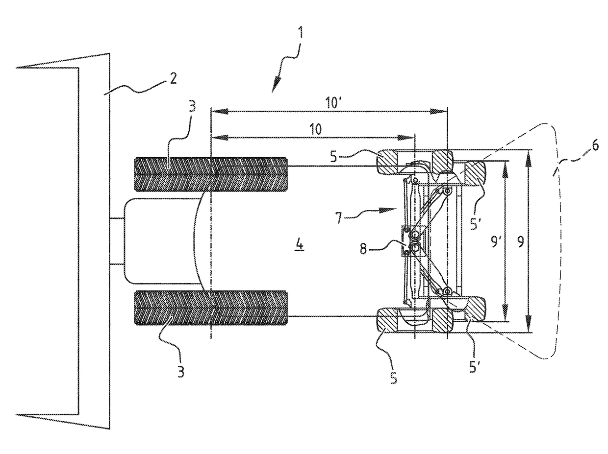
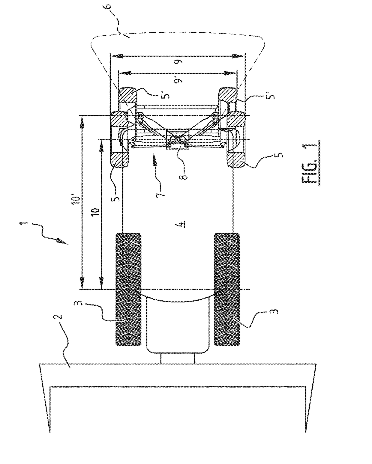
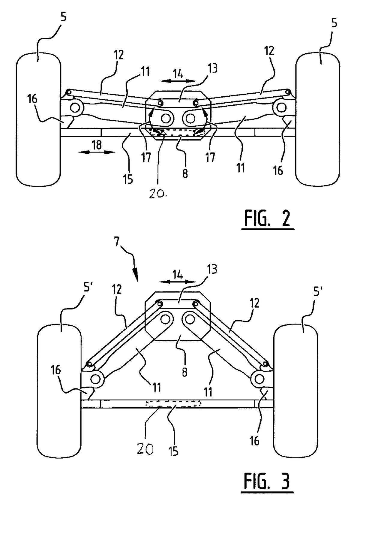
[0007]The back pair of wheels of the agricultural vehicle of the invention is connected to the frame via intermediate support elements. By rotating / pivoting these intermediate support elements with respect to the frame, the track width is adaptable in an alternative manner. However, tests have shown that adapting the track width in this manner has further unexpected advantages. By rotating / pivoting the intermediate support elements, not only the track width of the back pair of wheels is adapted, but also the wheel base, which is defined by the distance between the front wheels and the back wheels, is adapted. Particularly, the wheel base is enlarged when the track width is reduced. In this context, it is noted that the reduced track width is mainly intended for road use of the agricultural vehicle. By stretching the wheel base during road use, the steering behavior is more stable, since it is less responsive, which contributes to safety on road. On the other hand, when the back pair of wheels is in wide track mode, intended for field use for the agricultural vehicle, the smaller wheel base will have a positive effect on the turning radius of the agricultural vehicle.
[0011]Preferably the front pair of wheels defines a front track width and the first track width is larger than the front track width and the second track width is equal or smaller than the front track width. In such a configuration, the front pair of wheels can be provided with a fixed track width. This fixed track width is preferably limited by the requirements for road use. By providing the back pair of wheels with a first track width that is larger than the front track width, a higher stability during field use of the agricultural vehicle is obtained. By providing the back pair of wheels with a second track width that is equal or smaller than the first track width, the agricultural vehicle meets the requirement for travelling on the road.
[0012]Preferably each intermediate support element is pivotably connected to a central zone of the frame, the central zone being located at the back end of the vehicle. When the intermediate support elements are connected to a central zone at the back end of the frame, the back pair of wheels can be easily moved by rotating / pivoting the intermediate support elements between a position where the back pair of wheels show a larger track width and a smaller wheelbase, and a further position where the back pair of wheels show a smaller track width and a larger wheelbase.

Problems solved by technology

However, the track width for driving on the public roads is limited by legislations in many countries.
A drawback of the described system is that the maximum turning angle in a narrow track width position is limited.

Method used


Image

  • Agricultural vehicle support frame
  • Agricultural vehicle support frame
  • Agricultural vehicle support frame

Examples


Embodiment Construction

[0021]FIG. 1 shows a top view of an agricultural harvester 1. The agricultural harvester 1 has a header 2 that is, at least in field mode of the agricultural harvester 1, connected to a body 4 at a front end of the vehicle 1. The body 4 is supported by a front pair of wheels 3 and a back pair of wheels 5. In FIG. 1, the back pair of wheels 5 is shown in two positions. The back pair of wheels indicated with reference number 5 shows the first position and the back pair of wheels indicated with reference number 5′ shows the second position. The back pair of wheels is connected to the body 4 of the agricultural vehicle via a supporting system 7 that is described hereunder with reference to FIGS. 2 and 3. The supporting system 7 is connected to the body 4 and a central zone 8 at the back end of the vehicle 1.

[0022]The supporting system 7, described in more detail hereunder, allows the back pair of wheels 5 to move between the first position 5 and the second position 5′. Thereby, the firs...


PUM


Abstract

An Agricultural vehicle has a frame supported by a front pair of wheels and a back pair of wheels, wherein the back pair of wheels are steerable and wherein each wheel of the back pair of wheels is connected to the frame via a respective intermediate support element that is pivotable with respect to the frame in such a manner that the back pair of wheels are movable between a first position wherein the back pair of wheels defines a first track width and are positioned at a first distance from the front pair of wheels, and a second position wherein the back pair of wheels defines a second track width and are positioned at a second distance from the front pair of wheels, wherein the first track width is larger than the second track width and wherein the first distance is smaller than the second distance.

Description

[0001]This application claims the benefit of and priority to U.S. Provisional Application No. 62 / 117,549, filed Feb. 18, 2014, entitled “Agricultural Vehicle Support Frame”, which is hereby incorporated by reference in its entirety.FIELD OF THE INVENTION[0002]The present invention relates to an agricultural vehicle comprising frames supported by a front pair of wheels and a back pair of wheels, wherein the back pair of wheels is steerable.BACKGROUND OF THE INVENTION[0003]The width of an agricultural vehicle has an impact on the capacity that can be obtained from the machine. A trend in the design of agricultural vehicles, especially combines and other equipment used to traverse a field, is for the size of the machines to become larger, reducing the number of passes required to cover a field. Agricultural harvesters, such as combines, include a header and a feeder housing which remove the crop material from the field, gather the crop material and transport the crop material to a sepa...

Claims


Application Information

Patent Timeline
Patent Type & Authority Patents(United States)
IPC IPC(8): B60B35/10B62D7/18A01B63/00A01B73/00B62D49/06
CPCA01B63/006A01B73/00B60B35/10B62D7/18B62D49/0678B60B35/1036B60G2300/40
Inventor CLIFFORD, JIMMIE D.DUQUESNE, FRANK R. G.FARLEY, HERBERT M.
Owner BLUE LEAF I P INC
Learn More