Steering column

Active Publication Date: 2018-04-03
AGCO SA (FR)
23 Cites 0 Cited by

AI-Extracted Technical Summary

Problems solved by technology

It is also known to move the pedal relative to a fixed cylinder position...

Method used

[0032]In use the position of the steering column 30 can be altered by the four bar mechanism 52 rotating on its pivots 58. This has the effect of moving the steering wheel 32 laterally as viewed in FIG. 3....

Benefits of technology

[0013]Advantageously, this feature of the invention allows the brake pedal to move in unison with the steering wheel whilst the position of the brake pedal relative to the steering wheel remains largely constant. This ensures a consistent pedal feel between position...

Abstract

A steering column assembly for a vehicle, the assembly having a steering wheel for steering the vehicle, a brake pedal for operating the vehicle brakes, wherein the steering wheel and a pivot for the brake pedal are carried on a four bar mechanism mounted on the vehicle.

Application Domain

Controlling membersFoot actuated initiations +5

Technology Topic

Vehicle brakeControl theory +2

Image

  • Steering column
  • Steering column
  • Steering column

Examples

  • Experimental program(1)

Example

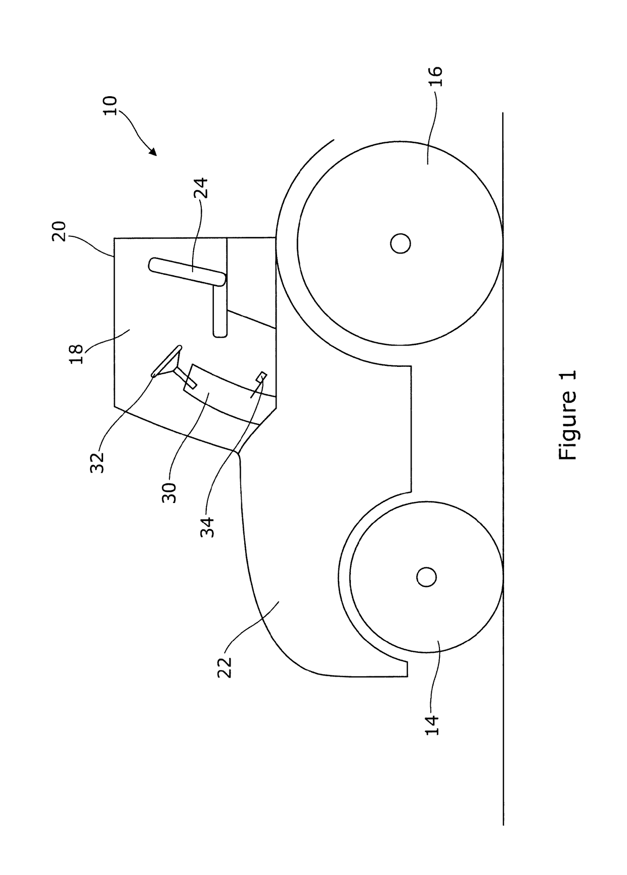
[0029]FIG. 1 shows a tractor 10 having front wheels 14, rear wheels 16, a cab 18, roof 20 and a hood 22. Within the cab 18 is a seat 24 and a steering column 30. The steering column 30 supports a steering wheel 32 and brake pedal 34. The other pedals and controls are not shown for clarity.
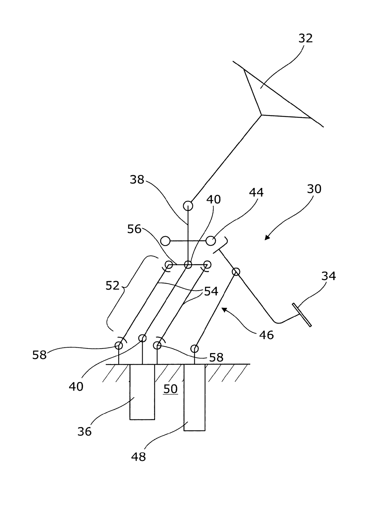
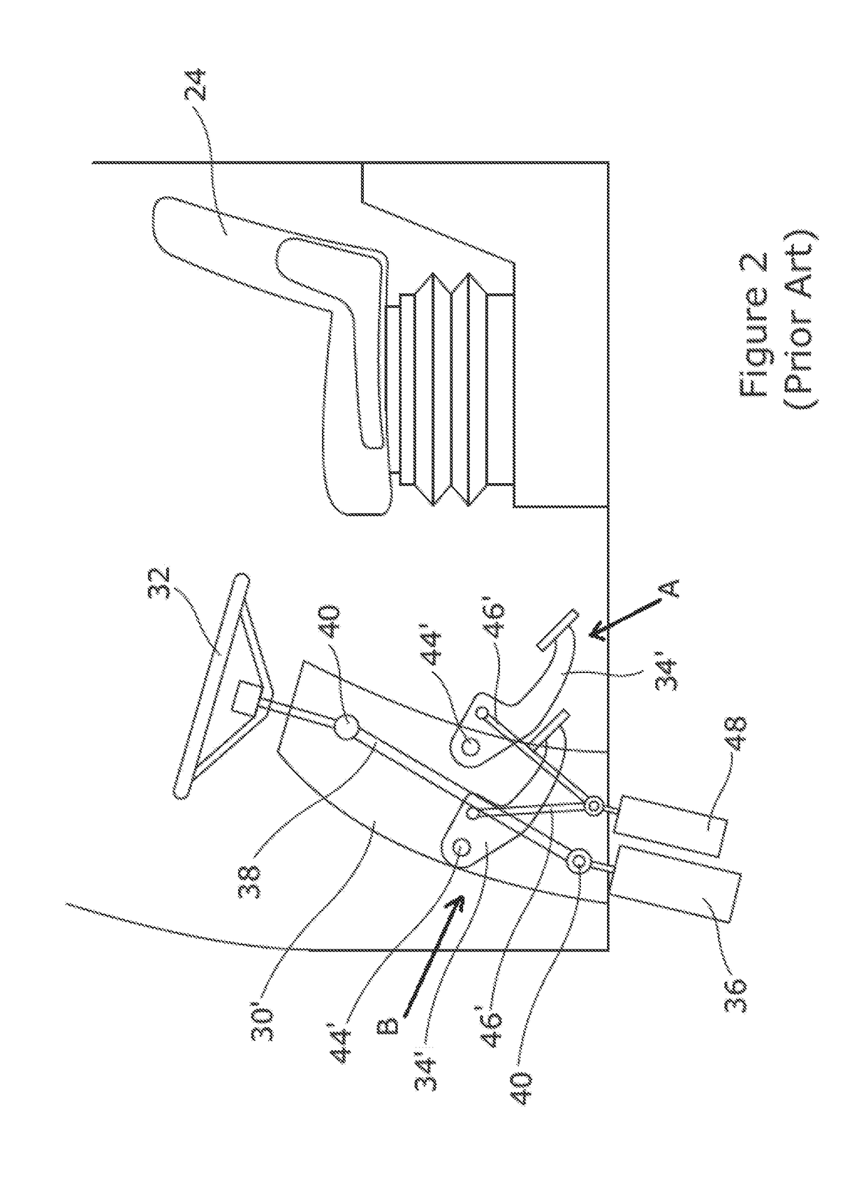
[0030]Turning now to FIG. 2 a prior art steering column 30′ is shown in greater detail. The steering wheel 32 operates a hydraulic steering unit 36 via shaft 38 supported by two universal joints 40. The brake pedal 34′ is shown in a first position A which corresponds to a first position of the steering column 34′ and a second position B which corresponds to a second position (not shown) of the steering column 34′. Pedal 34′ is carried on a pivot 44′ and operates a connecting rod 46′ which is connected to a brake cylinder 48 at its lower end. It can be seen that in moving the steering column 34′ from its first to second position the angle of the connecting rod 46′ changes substantially which alters the load applied to the brake cylinder 48 for a given load applied to the pedal 34′ by the operator. This leads to an inconsistent brake feel.
[0031]Turning now to FIG. 3, the steering column 30 of the present invention is intended as a replacement for the known column of FIG. 2. The steering column 30 has a steering wheel 32 and a brake pedal 34. The brake pedal 34 is linked to the brake cylinder 48 by connecting rod 46. The brake cylinder 48 is fixed to the tractor chassis indicated generally at 50. The brake pedal 34 is supported on the steering column by pivot 44. The pivot 44 and steering shaft 38 are supported by a four bar mechanism indicated generally at 52. The mechanism has two upright members 54 and a cross member 56. The lower ends of the upright members 54 are pivotally attached to the chassis 50 via pivots 58. The steering wheel 32 is connected to the hydraulic steering unit 36 by steering shaft 38 acting through universal joints 40.
[0032]In use the position of the steering column 30 can be altered by the four bar mechanism 52 rotating on its pivots 58. This has the effect of moving the steering wheel 32 laterally as viewed in FIG. 3. Furthermore the connecting rod 46 is caused to move in parallel with the upright members of the four bar mechanism. This ensures a more consistent pedal feel as the position of the steering column varies.
[0033]The four bar mechanism 52 is arranged to be substantially in line with the longitudinal direction of the tractor. Such an alignment allows for the steering column 30 to be adjusted along the longitudinal and vertical axes of the tractor.
[0034]It will be understood that the steering column may be provided with a locking mechanism (not shown), such that the steering column may be releasably locked in position, after adjustment.
[0035]The invention is not limited to the embodiment described herein, and may be modified or adapted without departing from the scope of the present invention.

PUM

no PUM

Description & Claims & Application Information

We can also present the details of the Description, Claims and Application information to help users get a comprehensive understanding of the technical details of the patent, such as background art, summary of invention, brief description of drawings, description of embodiments, and other original content. On the other hand, users can also determine the specific scope of protection of the technology through the list of claims; as well as understand the changes in the life cycle of the technology with the presentation of the patent timeline. Login to view more.

Similar technology patents

Receiving unit for computer

InactiveUS7173815B2increase reliability
Owner:SAMSUNG ELECTRONICS CO LTD

Wireless communication system, communication device, program, and integrated circuit

InactiveUS20120324308A1increase reliabilityfrequency utilization efficiency be improve
Owner:SHARP KK +1

Classification and recommendation of technical efficacy words

  • increase reliability
  • simplify assembly

Fanless computer with integrated display

InactiveUS7072179B1increase reliabilitylower maintenance cost
Owner:MICRO INDS CORP

Adjustable threshold assembly

InactiveUS20050210754A1reduce component costsimplify assembly
Owner:IMPERIAL PRODS

Battery pack

InactiveUS20090263711A1improve efficiencysimplify assembly
Owner:SAMSUNG SDI CO LTD

PACKAGING SOLUTIONS FOR DEVICES AND SYSTEMS COMPRISING LATERAL GaN POWER TRANSISTORS

ActiveUS20160307826A1facilitate interconnectionsimplify assembly
Owner:GAN SYST

Connection Device for Medium Conduits

ActiveUS20090127847A1simplify assemblyhigh reliability
Owner:VOSS AUTOMOTIVE

Double-row angular contact ball bearing

ActiveUS6957919B2simplify assembly
Owner:SCHAEFFLER TECH AG & CO KG
Why Eureka
Try Eureka