UV sanitizing assemblies with high dose features and methods for controlling the same

a technology of sanitizing assemblies and high doses, which is applied in the direction of water/sludge/sewage treatment, water treatment parameter control, chemistry apparatus and processes, etc., can solve the problem of less uv output, interference with matching the power level to the system demand, and overcooling of the lamp, so as to improve efficiency and reduce uvc energy , the effect of simple on/off flow detection

Active Publication Date: 2018-04-03
WATTS REGULATOR
View PDF23 Cites 9 Cited by
  • Summary
  • Abstract
  • Description
  • Claims
  • Application Information

AI Technical Summary

Benefits of technology

[0015]In view of the above, it can be appreciated that it is beneficial to be able to adjust the power level of the lamp in response to the demand of the fluid treatment system. In other words, dimming the lamp when the system demand requires less UVC energy would improve efficiency. Dimming control based on simple on / off flow detection (e.g., by means of a pressure switch) and also by a more sophisticated technique that includes use of water temperature is described in U.S. Pat. No. 5,547,590 issued on Aug. 20, 2996.
[0017]The subject technology addresses and overcomes these concerns. In one embodiment, the subject technology is directed to improving the stability of output efficiency of a mercury vapour UV lamp over a range of operating temperatures and input power levels. Additionally, the subject technology can control the electrical energy input to a mercury vapour UV lamp in a manner to improve the stability of the UV light output efficiency over a range of operating temperatures and input power levels.
[0019]Further, a plurality of sensor inputs may be used to develop a refined algorithm that can function effectively with a reduced number of sensor inputs. For example, UV output, fluid temperature, and time data may be analyzed to the extent that only time and fluid temperature are required to achieve near optimum lamp operation across a range of power settings. Still further, another embodiment monitors the temperature of the liquid mercury droplets more directly. For example, the monitoring is done by using an infra-red sensor, which creates more precisely control of the lamp near optimum lamp operation across a range of power settings.
[0022]Additionally, as noted above, there are also problems associated with the vessels for UV treatment methods in that dosage is not very efficient, which results in certain fluid elements having improper dosage due to relatively quicker transit through the system and further distance from the UV source. The present technology provides low-cost features that reduce at least one phenomenon that leads to low-dose elements exiting the treatment zone.

Problems solved by technology

Unfortunately, the extreme temperature dependence of these mercury vapour lamps interferes with matching the power level to the system demand.
For example, if the lamp is already in an overheated condition then increasing the lamp arc current will cause further overheating and may actually result in less UV output.
However, simply reducing lamp arc current may result in overcooling of the lamp.

Method used


Image

  • UV sanitizing assemblies with high dose features and methods for controlling the same
  • UV sanitizing assemblies with high dose features and methods for controlling the same
  • UV sanitizing assemblies with high dose features and methods for controlling the same

Examples


Embodiment Construction

[0033]The subject technology overcomes many of the prior art problems associated with UV sanitizing assemblies and methods for operating the same. The advantages, and other features of the systems and methods disclosed herein, will become more readily apparent to those having ordinary skill in the art from the following detailed description of certain preferred embodiments taken in conjunction with the drawings which set forth representative embodiments of the present invention and wherein like reference numerals identify similar structural elements. All relative descriptions herein such as left, right, up, and down are with reference to the Figures, and not meant in a limiting sense.

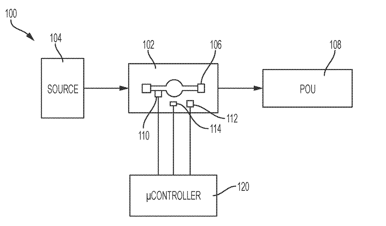
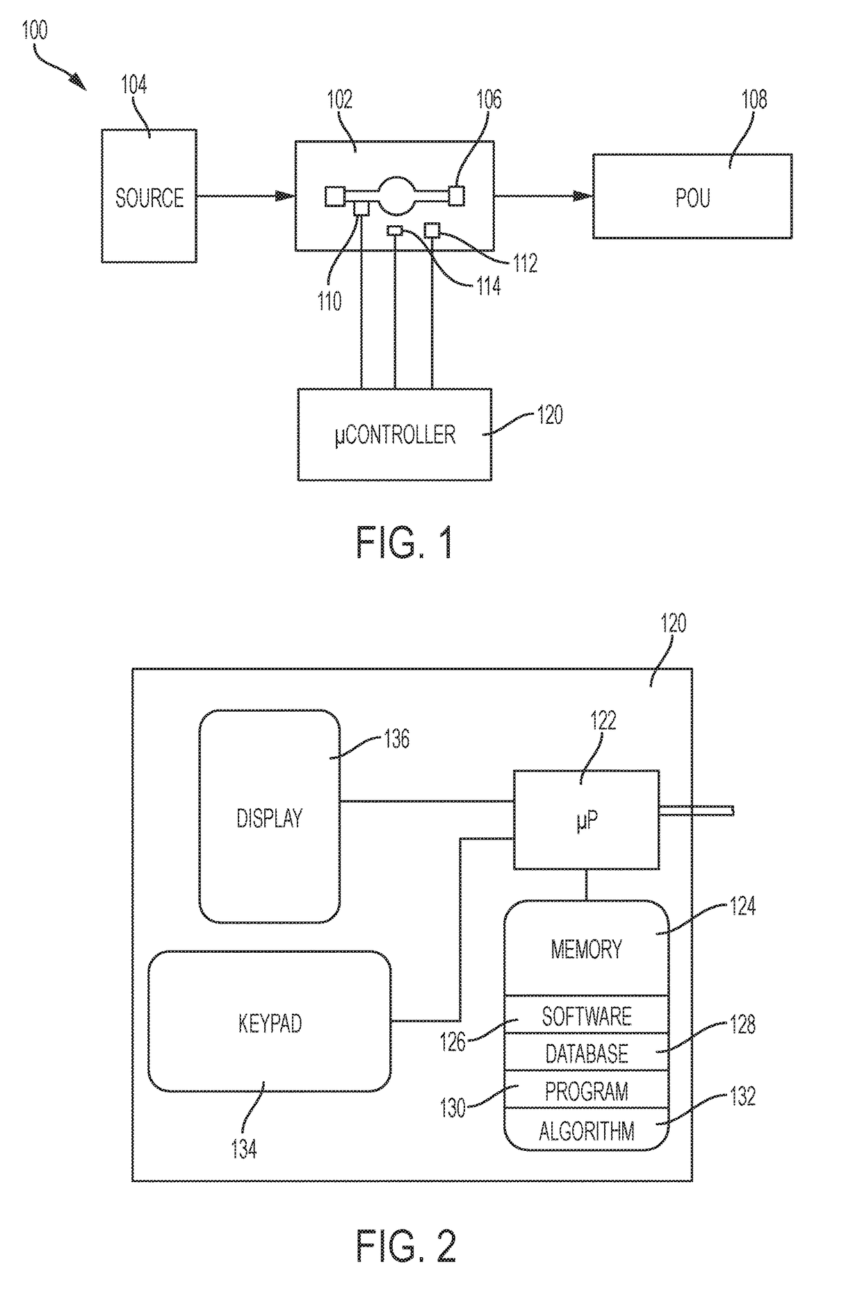
[0034]Referring now to FIG. 1, a diagram showing water purifying system 100 deploying an ultraviolet (UV) lamp assembly 102 in accordance with the subject disclosure is shown. The water purifying system 100 efficiently treats water with UV radiation to kill organisms among other benefits. The following ...


PUM

PropertyMeasurementUnit
wavelengthaaaaaaaaaa
poweraaaaaaaaaa

Abstract

A purifying system for treating a fluid with UV light including a housing defining: a chamber having a treatment zone; an inlet; and an outlet. The light source supplies UV light to the treatment zone. The inlet, the tubular housing, or the outlet may extend inward into the chamber so that the fluid passes close to the light source and has a relatively increased duration in the treatment zone. The purifying system may also have a sensor coupled to the housing or light source for generating a first signal indicative of a first parameter of the treatment zone. A microcontroller can control the light source based on a signal from the sensor and data characterizing the light source. The microcontroller may also vary operation of the light source and collect data to create the data characterizing the light source.

Description

CROSS-REFERENCE TO RELATED APPLICATION[0001]This application claims priority to U.S. Provisional Patent Application No. 62 / 027,993, filed Jul. 23, 2014 and U.S. Provisional Patent Application No. 62 / 150,827, filed Apr. 21, 2015, which are incorporated herein by reference.BACKGROUND OF THE DISCLOSURE[0002]1. Field of the Disclosure[0003]The subject disclosure relates to assemblies and methods for sanitizing fluid such as water using UV light and, more particularly to extended UV sanitizing chamber ports that improve dosage as well as systems and methods for characterizing the sanitizing assemblies to improve operational efficiency.[0004]2. Background of the Related Art[0005]Generally, treatment of fluids via irradiation with ultraviolet light is known. The treatment of fluids, including disinfection of water, within an enclosed treatment zone that is irradiated with ultraviolet light (hereafter abbreviated to “UV” or UV light”) is shown in FIG. 6, which is a cross-sectional view of a...

Claims


Application Information

Patent Timeline
Patent Type & Authority Patents(United States)
IPC IPC(8): C02F1/32
CPCC02F1/325C02F2201/326C02F2209/40C02F2209/006C02F2209/02C02F2201/3223H05B47/105
Inventor SCHMITT, CRAIGSARCHESE, MICHAELPOWELL, COLIN
Owner WATTS REGULATOR
Why Eureka
Try Eureka