Automatic driving vehicle system
a technology of automatic driving and vehicle system, applied in the direction of instruments, scene recognition, navigation instruments, etc., can solve the problem that the ride quality of the vehicle sometimes becomes wors
- Summary
- Abstract
- Description
- Claims
- Application Information
AI Technical Summary
Benefits of technology
Problems solved by technology
Method used
Image
Examples
first embodiment
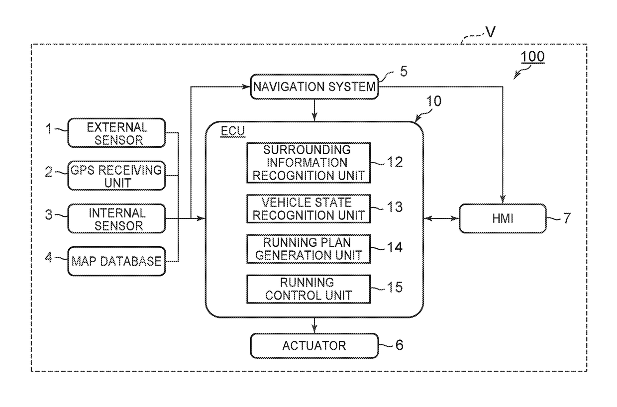
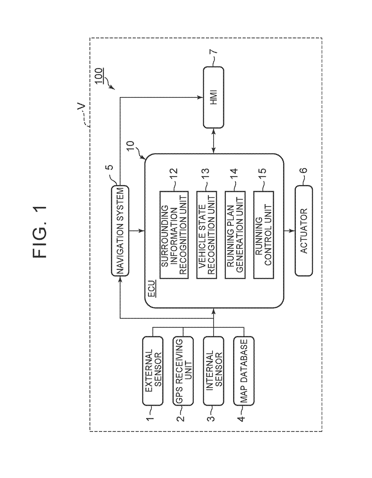
[0028]FIG. 1 is a block diagram showing a configuration of an automatic driving vehicle system 100 according to a first embodiment. As shown in FIG. 1, the automatic driving vehicle system 100 is mounted in a vehicle V such as an automobile. The automatic driving vehicle system 100 includes an external sensor 1, a GPS [Global Positioning System] receiving unit 2, an internal sensor 3, a map database 4, a navigation system 5, an actuator 6, an ECU [Electronic Control Unit]10, and an HMI [Human Machine Interface]7.
[0029]The external sensor 1 is detection equipment to detect the surrounding information of the vehicle V. The external sensor 1 includes at least one of a camera, a radar and a LIDAR [Laser Imaging Detection and Ranging].
[0030]The camera is an imaging device to image the surround of the vehicle V. The camera, for example, is provided on the vehicle interior side of the vehicle V relative to a windshield. Alternatively, the camera may be provided on the exterior of the vehic...
second embodiment
[0096]Next, a second embodiment will be described. In the description of the embodiment, differences from the first embodiment are described in detail. For elements identical or corresponding to those in the first embodiment, identical reference characters are used, and repetitive descriptions are omitted. FIG. 8 is a block diagram showing a configuration of an automatic driving vehicle system 100A according to the second embodiment. The automatic driving vehicle system 100A includes the external sensor 1, the GPS receiving unit 2, the internal sensor 3, the map database 4, the navigation system 5, the actuator 6, a first ECU 10A, a second ECU 10B, and the HMI 7. Here, the embodiment is different from the first embodiment in that the running plan generation unit 14 and the running control unit 15 are included in different ECUs. Specifically, the running control unit 15 may be included in a second ECU.
[0097]The first ECU 10A and the second ECU 10B control the automatic running of the...
third embodiment
[0104]Next, a third embodiment will be described. In the description of the embodiment, differences from the first embodiment are described in detail. For elements identical or corresponding to those in the first embodiment, identical reference characters are used, and repetitive descriptions are omitted. FIG. 9 is a block diagram showing a configuration of an automatic driving vehicle system 100B according to the third embodiment. The automatic driving vehicle system 100B includes the external sensor 1, the GPS receiving unit 2, the internal sensor 3, the map database 4, the navigation system 5, an actuator unit 60, an ECU 20, and the HMI 7. Here, the embodiment is different from the first embodiment mainly in that an actuator control unit (actuator controller) 62 of the actuator unit 60 controls an actuator 61 based on the control band.
[0105]The ECU 20 controls the automatic running of the vehicle V. The ECU 20 is an electronic control unit including a CPU, a ROM, a RAM and the li...
PUM
 Abstract
Description
Claims
Application Information
 - R&D
- Intellectual Property
- Life Sciences
- Materials
- Tech Scout
- Unparalleled Data Quality
- Higher Quality Content
- 60% Fewer Hallucinations
Browse by: Latest US Patents, China's latest patents, Technical Efficacy Thesaurus, Application Domain, Technology Topic, Popular Technical Reports.
© 2025 PatSnap. All rights reserved.Legal|Privacy policy|Modern Slavery Act Transparency Statement|Sitemap|About US| Contact US: help@patsnap.com


