
Cushion body

a technology of cushion body and foam, which is applied in the field of cushion body, can solve the problems of inability to progress in weight reduction, inferior recyclability of polyurethane foam, and increased weight of seat frame, so as to improve recyclability, reduce weight, and improve the effect of recyclability

Active Publication Date: 2018-04-10
TOYO SEAT +1
View PDF13 Cites 2 Cited by
  • Summary
  • Abstract
  • Description
  • Claims
  • Application Information

AI Technical Summary

Benefits of technology

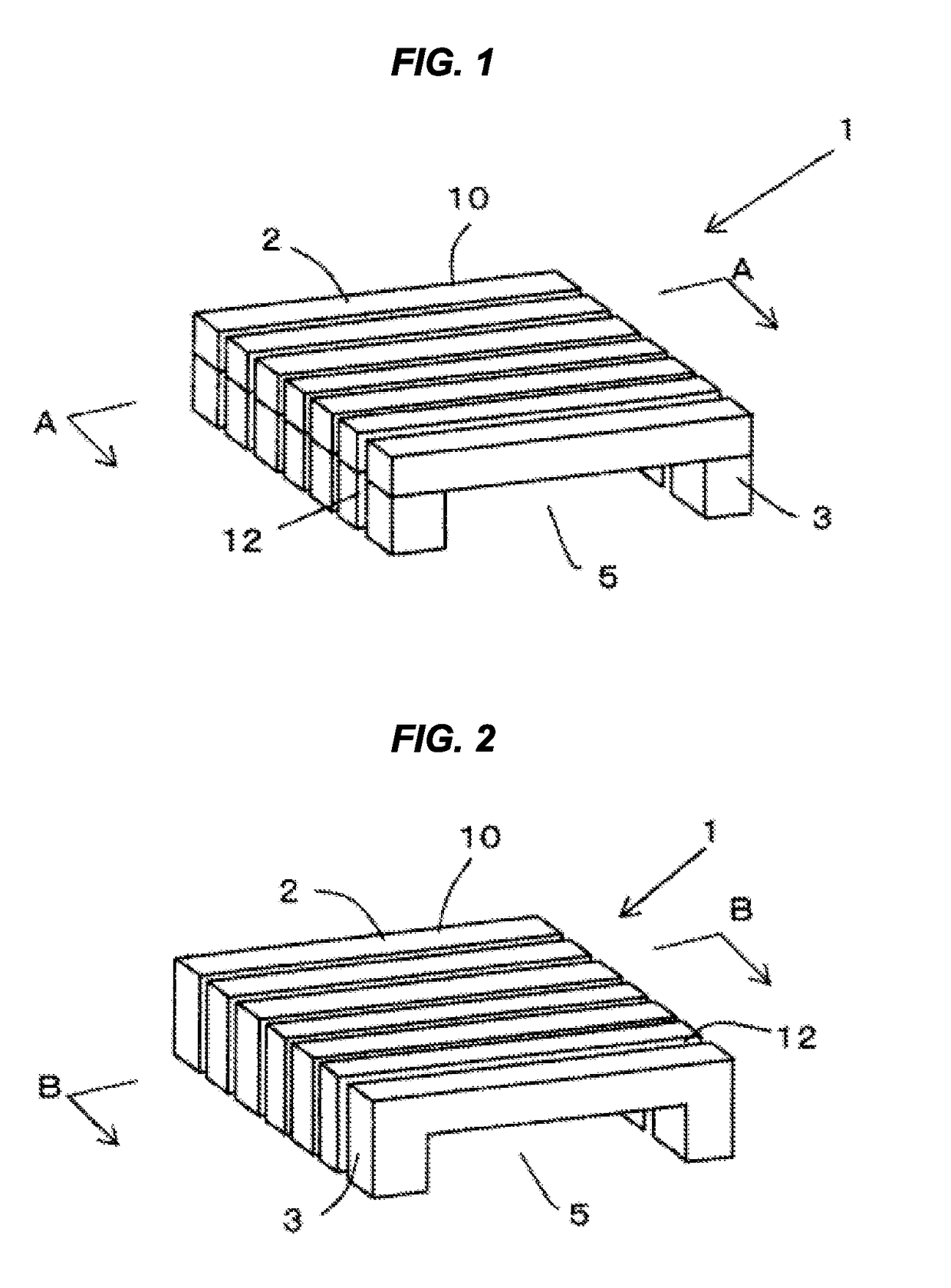
[0038]In the invention of the cushion body 1 described in the first aspect, the polyurethane foam used generally and conventionally can be substituted by the synthetic resin foam, which results in the weight reduction and the improvement in recyclability. Further, in spite of the use of the synthetic resin foam that is relatively hard and inferior in cushioning properties, fitting properties, and creep resistance properties, it is possible to provide the synthetic resin foam with high cushioning properties, high fitting properties, and high degree of freedom of design. The body of the seated person and the supine posture person can be therefore supported appropriately, and the high comfort can be obtained. The favorable creep resistance properties equivalent to those of the conventional polyurethane foam are exerted even with long-time use, thereby exerting the effect of high marketability.
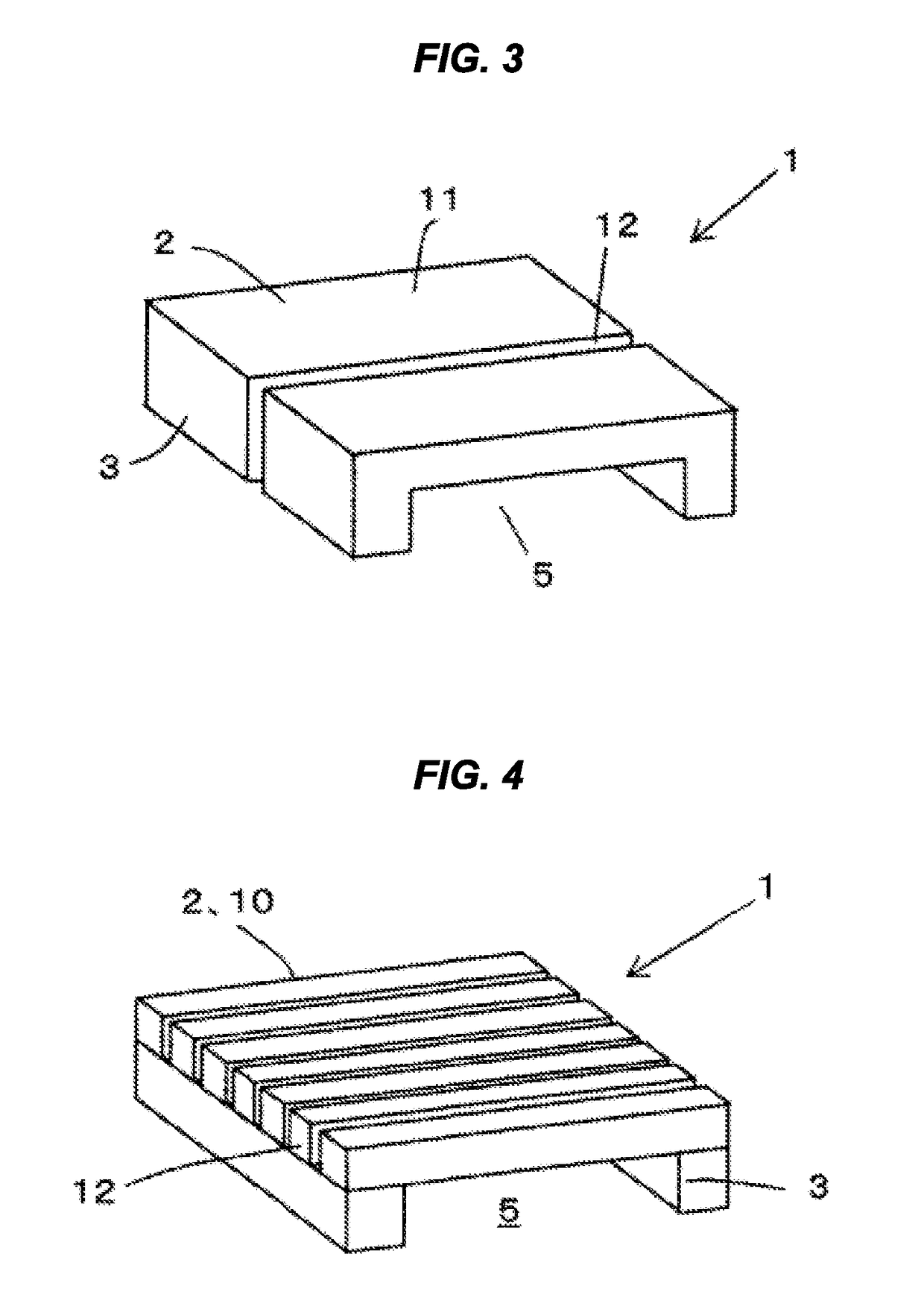
[0039]The cushion body 1 described in the second aspect achieves an effect of forming a space which can deforms by bending downward in the supporting body 2 by the leg body 3 since the supporting body 2 is supported by the leg body 3 extended from the supporting body 2, as well as achieving the same effects as those of the invention described in the first aspect.
[0040]The cushion body 1 described in the third aspect achieves an effect of forming a space which can deforms by bending downward in the supporting body 2 by the frame 50 since the supporting body 2 is supported by the frame 50, as well as achieving the same effects as those of the invention described in the first aspect.
[0041]The cushion body 1 described in the fourth aspect achieves the same effects as those of any one of the first to third aspects 3. Further, in the case that the distance between both ends of the supporting body 2 can not be sufficiently secured by the compact cushion body, and a sufficient deflection can not be obtained by the load caused by the seated person or the supine posture person, it is possible to enlarge the substantial distance between both ends of the supporting body 2 at the bending deformation receiving time and obtain the sufficient deflection, by forming the supporting body 2 into the circular arc shape or the bent shape constructed by the combination of the straight line portions obtained by bending the straight lines at the optional angle, instead of the linear shape. As a result, it is possible to enhance the degree of freedom of the design.
[0042]The cushion body 1 described in the fifth aspect achieves the same effects as those of any one of the first to fourth aspects. Further, in the case that the supporting body 2 is constructed by the laminated structure, it is possible to enhance the cushioning properties in the side with which the seated person or the supine posture person comes into contact, by making the supporting body 2 in the seated person side or the supine posture person side with the material having more flexibility. The supporting body 2 can be fitted to an outer shape of the body at the seating time or the supine posture time by conforming the shape of the supporting body 2 in the seated person side or the supine posture side to the shape of the body.
[0043]Further, in the case that the supporting body 2 is the integrated structure which is constructed by the combination of the different kinds of materials set every position, for example, in the case that the supporting body 2 has the strongly pressed position and the weakly pressed position applied by the seated person or the supine posture person, the deflection amount of the supporting body 2 can be uniformized over an entire region by using the synthetic resin foam having a higher density at the strongly pressed position of the supporting body 2 and using the synthetic resin foam having a lower density at the weakly pressed position. As a result, it is possible to support the body of the seated person or the supine posture person at a preferable position.

Problems solved by technology

However, there has been a problem that the polyurethane foam is inferior in recyclability.
Therefore, there has been a problem that the weight reduction does not progress.
As a result, there has been a problem that the weight of the seat frame tends to be increased and the weight reduction effect a whole is not sufficient in spite of the light weight of the net material itself which corresponds to the conventional cushion material, the weight of the seat frame tends to be increased.
Further, the cushioning properties of the net material have been obtained mainly by elongation of the material, and therefore limited.
A slack has occurred due to long-time use, which has tended to deteriorate marketability.
Still further, since the structure has been configured such that a flat net material is extended over the seat frame, the basic form of the seat cushion is flat, and it has been difficult to obtain a three-dimensional shape which is necessary for supporting a body of the occupant at an optimal position.
As a result, there has been a problem of making the occupant uncomfortable.
This has been because an unstable hammock-form net material could not stably support the body of the occupant when a lateral G has been applied to the occupant due to movement of a vehicle.

Method used


Image

  • Cushion body
  • Cushion body
  • Cushion body

Examples


Embodiment Construction

[0089]A description will be given below of an embodiment of a cushion body 1 according to the present invention.

[0090]The cushion body 1 according to the present invention can be used as a constructing element of a cushion for a vehicular seat of a vehicle, a ship and an airplane, a sofa, a chair, a floor cushion, a bed, a sleeping car, a mattress, an under a futon mattress, a pillow and a mat, which are used at the seating time and the supine posture time of a person.

[0091]The cushion body 1 is provided with a plurality of rod-like elements 10 or flat plate-like elements 11 supporting bodies 2 which are constructed by a synthetic resin foam having a bending deflection amount equal to or larger than 20 mm and a load 9 between 2 and 100 N at the 20 mm deflection time, both the bending deflection amount and the load being measured in accordance with a method described in JIS K7221-2: 2006, and the cushion body 1 is structured such that a space portion 5 is formed below the supporting ...


PUM


Abstract

The present invention solves the problem of realizing a lighter cushion body that has ample cushioning properties when a person sits or lies thereon by: providing a plurality of rod-shaped or flat plate-shaped support bodies (2) comprising a synthetic resin foam that has a bending deflection amount of 20 mm or more as measured according to the method described in JIS K7221-2:2006 and a pressing force of 2-100 N at 20 mm of deflection, and legs (3) on which the support bodies (2) are placed or fixed; using the support bodies and the legs to form a space (5) that makes it possible to bend and deform the support bodies; and arranging the plurality of rod-shaped or flat plate-shaped support bodies (2) in a row so as to be deformable.

Description

TECHNICAL FIELD[0001]The present invention relates to a cushion body which is used as a constructing element for a vehicular seat of a vehicle, a ship and an airplane, a sofa, a chair, a floor cushion, a bed, a sleeping car, a mattress, a under a futon mattress, a pillow and a mat, which are used at the seating time and the supine posture time of a person, the cushion body promoting weight reduction, being rich in recyclability and being rich in comfortable sit feeling and comfortable sleep feeling.BACKGROUND ART[0002]Generally, the cushion body has a structure in which a soft cushion material such as polyurethane foam is mounted on a structure body finally supporting pressure of a wire or a flat plate-like supporting body extended to a frame body, and a whole of them is covered with a surface cover. Further, the structure body does not inhere in the floor cushion and the mattress of the bed themselves, however, the floor cushion and the mattress of the bed are generally used by bei...

Claims


Application Information

Patent Timeline
Patent Type & Authority Patents(United States)
IPC IPC(8): A47C21/00A47C7/18B60N2/64A47C7/02A47G9/10A47C27/14B60N2/70
CPCB60N2/7094A47C7/021A47C7/18A47G9/10B60N2/643B60N2/646A47C27/14A47G2009/1018
Inventor ITO, HIROYUKIMURATA, SEISHIROSHIOYA, SATORUIMAI, TAKASHI
Owner TOYO SEAT
Learn More