Magnetoresistance effect element and magnetic memory device

a magnetic memory device and effect element technology, applied in the field of magnetoresistance effect element and magnetic memory device, can solve the problems of increasing the size of the memory cell, difficult to achieve highly symmetric rewrite property, and difficult to achieve highly symmetric retention property, and achieve high speed and symmetric rewrite property and retention property

Active Publication Date: 2018-04-10
TOHOKU UNIV
View PDF30 Cites 5 Cited by
  • Summary
  • Abstract
  • Description
  • Claims
  • Application Information

AI Technical Summary

Benefits of technology

[0037]The present disclosure can provide a magnetoresistance effect element and a magnetic memory device that are small, that achieve highly symmetric rewrite property and retention property, and that can allow for write at a high speed.

Problems solved by technology

Therefore, it is difficult to achieve highly symmetric rewrite property.
Accordingly, it is difficult to achieve highly symmetric retention property.
Therefore, the intermediate layer is required to be formed longwise in the short direction of the second outer layer, resulting in an increase in the size of a memory cell.
Furthermore, the laminate in Patent Literature 2, in which the direction of magnetization is inverted by precession, thus has the problems of an increase in threshold current in a nanosecond domain and difficulty in write at a high speed.

Method used


Image

  • Magnetoresistance effect element and magnetic memory device
  • Magnetoresistance effect element and magnetic memory device
  • Magnetoresistance effect element and magnetic memory device

Examples


embodiment 1

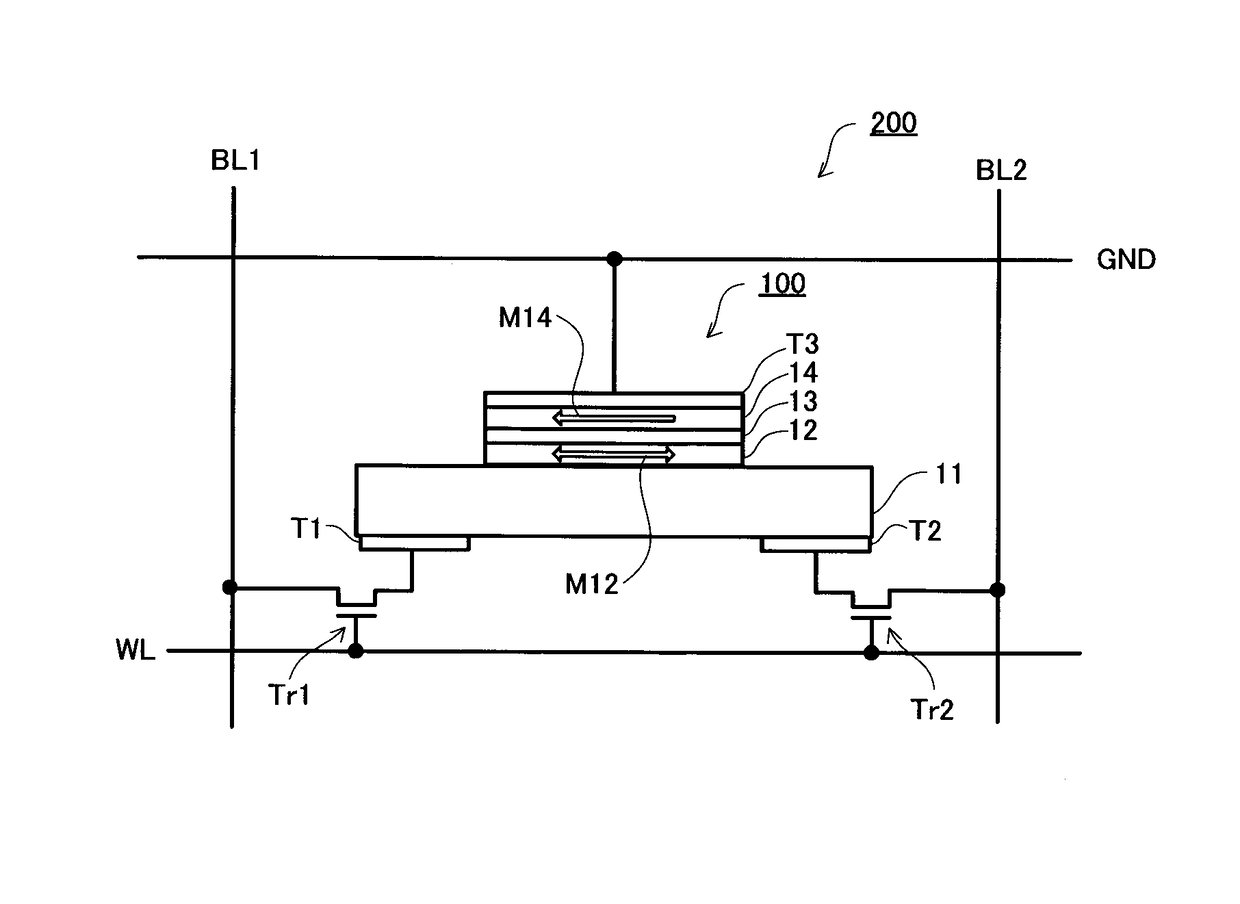
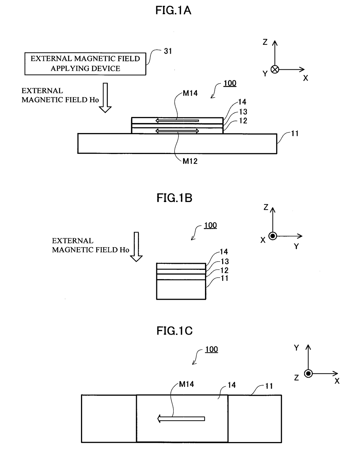
[0087]Hereinafter, a magnetoresistance effect element according to Embodiment 1 is described with reference to FIG. 1 to FIG. 5. FIG. 1A illustrates a front view of a magnetoresistance effect element 100 according to Embodiment 1, FIG. 1B illustrates a side view thereof, and FIG. 1C illustrates a plan view (top view) thereof. The magnetoresistance effect element 100 includes a heavy metal layer 11, a recording layer 12, a barrier layer 13 and a reference layer 14 that are laminated. The longitudinal (elongation) direction (the left / right direction of the page of FIG. 1A) of the heavy metal layer 11 is defined as the X-axis direction. The short direction (the depth of the page of FIG. 1A) of the heavy metal layer 11 is defined as the Y-axis direction. The height direction (the upward / downward direction in the page of FIG. 1A) in which the respective layers of the magnetoresistance effect element 100 are laminated is defined as the Z-axis direction.

[0088]The heavy metal layer (conduct...

embodiment 2

[0135]It is necessary to stably fix the direction of the magnetization M14 of the reference layer 14 in order to stably write and read the stored data in the magnetoresistance effect element 100 according to Embodiment 1. It is effective that the reference layer 14 includes a laminated ferri-coupled layer in order to stabilize the magnetization M14 of the reference layer 14.

[0136]Hereinafter, an embodiment of a magnetoresistance effect element 101 including a laminated ferri-coupled layer as a reference layer 14 is described with reference to FIG. 9A to FIG. 9C.

[0137]In the present embodiment, the reference layer 14 has a laminated structure where a ferromagnetic layer 14a, a coupling layer 14b and a ferromagnetic layer 14c are laminated and laminated ferri-coupled. The ferromagnetic layer 14a and the ferromagnetic layer 14c are antiferromagnetically coupled by the coupling layer 14b. Other elements are essentially the same as in Embodiment 1.

[0138]It is desirable to use a ferromagn...

modified embodiment 1

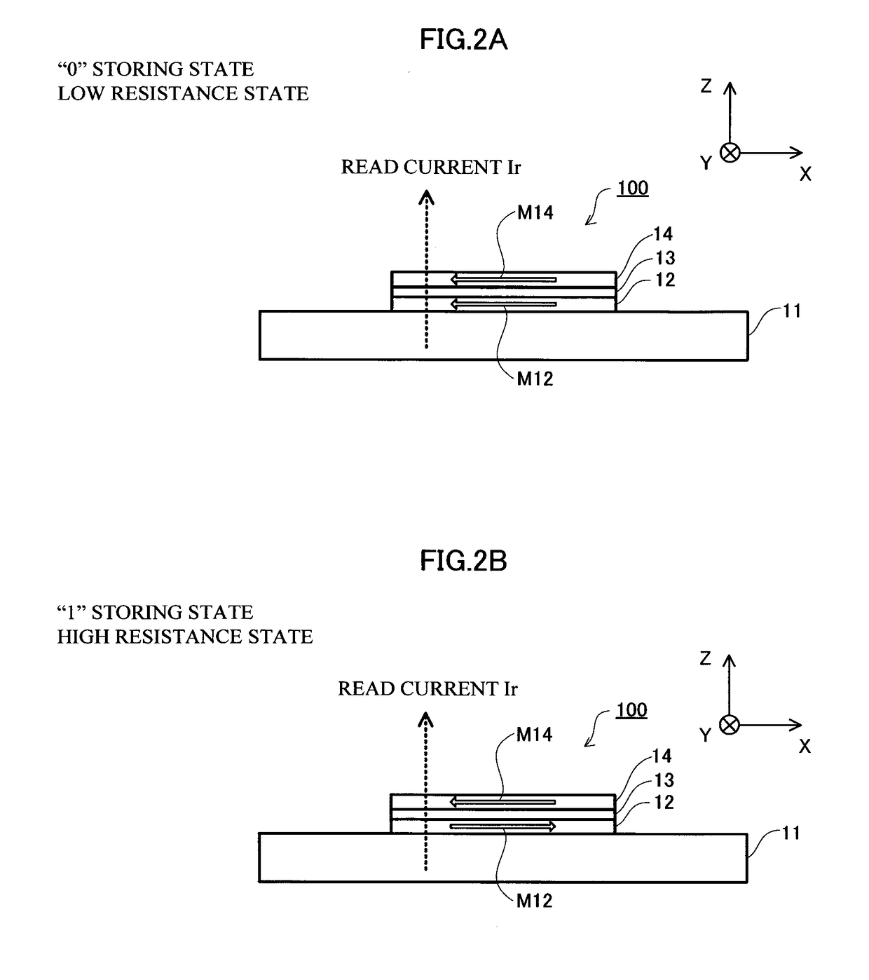
[0154]Allocation of the resistance and the data of the magnetoresistance effect element is arbitrarily determined, and data “1” and data “0” may also be allocated to a low resistance state and a high resistance state, respectively.


PUM


Abstract

A magnetoresistance effect element (100) includes a heavy metal layer (11) that includes a heavy metal and that is formed to extend in a first direction, a recording layer (12) that includes a ferromagnetic material and that is provided adjacent to the heavy metal layer (11), a barrier layer (13) that includes an insulating material and that is provided on the recording layer (12) with being adjacent to a surface of the recording layer (12) opposite to the heavy metal layer (11), and a reference layer (14) that includes a ferromagnetic material and that is provided adjacent to a surface of the barrier layer (13), the surface being opposite to the recording layer (12). The direction of the magnetization of the reference layer (14) has a component substantially fixed in the first direction, and the direction of the magnetization of the recording layer (12) has a component variable in the first direction. A current having a direction same as the first direction is introduced to the heavy metal layer (11) to thereby enable the magnetization of the recording layer (12) to be inverted.

Description

[0001]This is a National Phase Application filed under 35 U.S.C. § 371, of International Application No. PCT / JP2015 / 071562, filed Jul. 29, 2015.TECHNICAL FIELD[0002]This disclosure relates to a magnetoresistance effect element and a magnetic memory device.BACKGROUND ART[0003]A spin-transfer torque magnetic random access memory (STT-MRAM) has attracted attention as a next-generation nonvolatile memory that achieves a high speed and high rewrite endurance. STT-MRAM is a memory where a magnetic tunneling junction element (MTJ element) being a resistance change type storage element is used.[0004]Patent Literature 1 discloses a laminate suitable for a memory cell of a 3-terminal type STT-MRAM. This laminate has a structure where a first outer layer including a non-magnetic material, an intermediate layer (recording layer) including a magnetic material and a second outer layer including a non-magnetic material are laminated. A reference layer including a magnetic material for read is lami...

Claims


Application Information

Patent Timeline
Patent Type & Authority Patents(United States)
IPC IPC(8): G11C11/00H01L43/08H01L43/10G11C11/16H01L27/22H01L43/02
CPCH01L43/08G11C11/1673H01L43/10H01L27/228H01L43/02G11C11/1675H01L27/105H01L29/82G11C11/161G11C11/18H10B61/22H10N50/80H10N50/10H10N50/85
Inventor FUKAMI, SHUNSUKEZHANG, CHAOLINGANEKAWA, TETSUROOHNO, HIDEOENDOH, TETSUO
Owner TOHOKU UNIV
Why Eureka
Try Eureka