Floor panel

a technology for flooring and panels, applied in the field of floor panels, can solve the problem of insufficient rigidity of concrete itself, and achieve the effect of excellent design and easy production

Active Publication Date: 2018-04-17
KANA FURETSUKUSU KOOHOREESHON
View PDF14 Cites 9 Cited by
  • Summary
  • Abstract
  • Description
  • Claims
  • Application Information

AI Technical Summary

Benefits of technology

[0030]According to the floor panel of the present invention, the floor panel can be light-weighted while desired strengths for the floor panel are established. Such floor panel can be readily produced without any complicated processes.
[0031]Moreover, according to the present invention, the peripheral surface of the floor panel can be protected, for example, on the side surfaces and corners of the floor panel. Thereby, the floor panel can be prevented from being damaged during the transport, storage, application or use of the panel.
[0032]In addition, according to the present invention, a floor panel having an excellent design can be provided.

Problems solved by technology

Herein, concrete itself has insufficient rigidity, therefore, it causes problems.

Method used


Image

  • Floor panel
  • Floor panel
  • Floor panel

Examples


embodiment 1

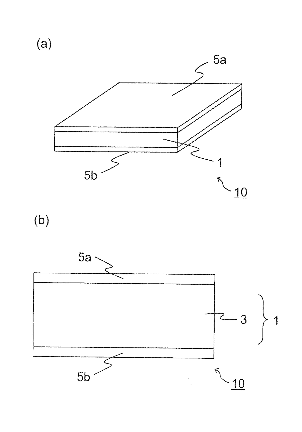
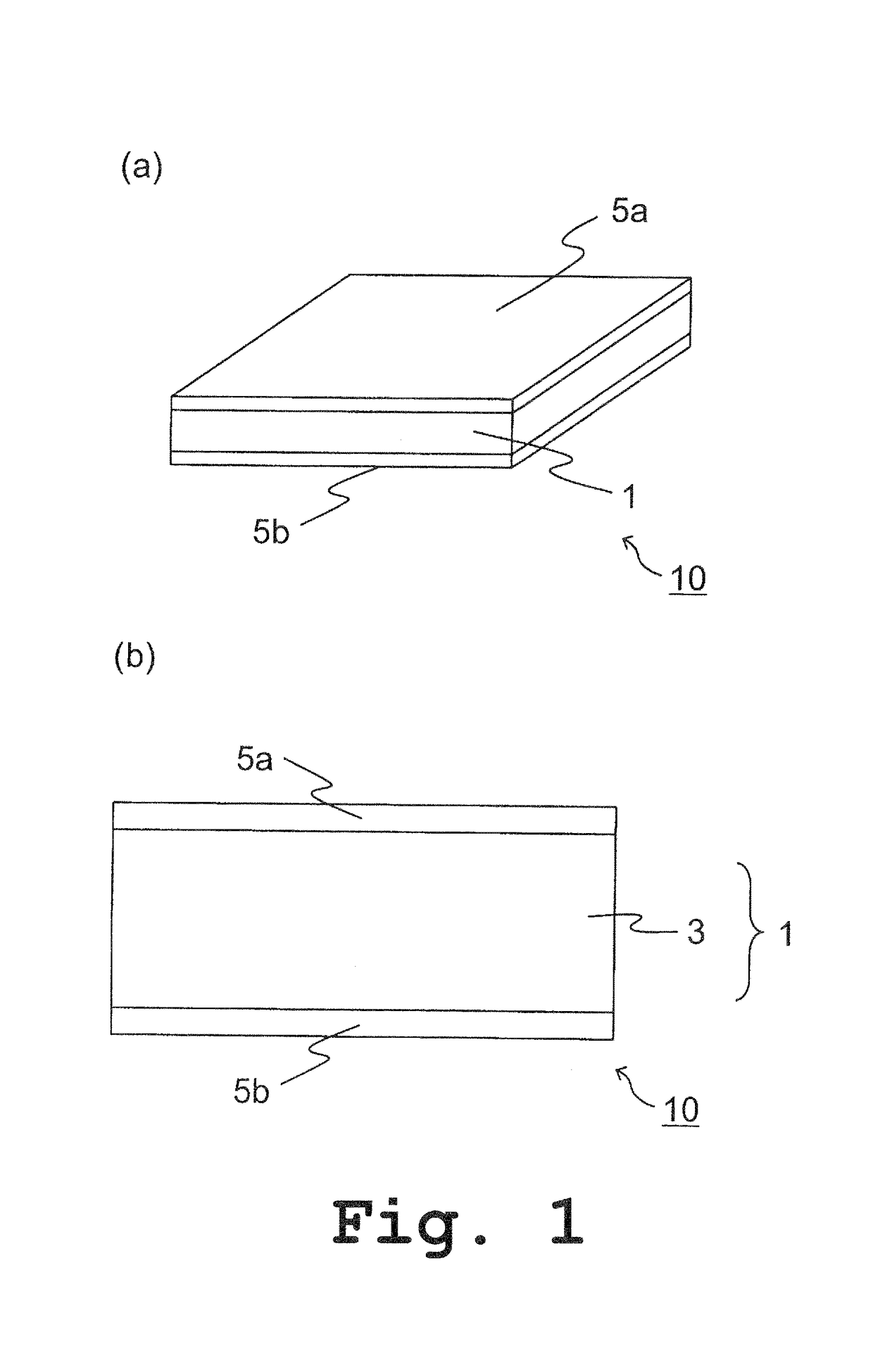
[0051]As shown in FIG. 1, a floor panel 10 as one embodiment according to the present invention comprises a foamed cement board 1; a top plate 5a attached to an upper surface the foamed cement board 1; and a bottom plate 5b attached to a lower surface of the foamed cement board 1. The floor panel 10 can be used such that the top plate 5a is located as a front surface (or a flooring surface) of the floor panel, and that the bottom plate 5b is located as a back surface of the floor panel.

[0052]In this embodiment, the foamed cement board 1 is comprised of a foamed cement layer 3. Herein, the top plate 5a and the bottom plate 5b are attached to an upper surface and a lower surface of the foamed cement layer 3, respectively. However, as long as the foamed cement board 1 comprises at least one foamed cement layer, the foamed cement board 1 may comprise other constituting part(s) (see, for example, Embodiment 2).

[0053]The foamed cement layer 3 is comprised of a material comprising at least...

embodiment 2

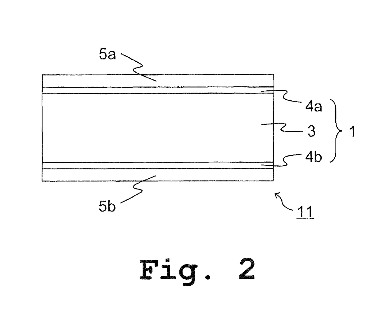
[0101]As shown in FIG. 2, the floor panel 11 according to this embodiment, which is same or similar to the floor panel 10 as Embodiment 1, comprises a foamed cement board 1; a top plate 5a attached to an upper surface of the foamed cement board 1; and a bottom plate 5b attached to a lower surface of the foamed cement board 1. The floor panel 11 may be used so that the top plate 5a is located as a front surface (or a flooring surface) of the floor panel and so that the bottom plate 5b is located as a back surface of the floor panel.

[0102]However, in this embodiment, the foamed cement board further comprises a fiber reinforced resin layers 4a formed on one side of the foamed cement layer 3 and a fiber reinforced resin layer 4b formed on the other side of the foamed cement layer 3, and the top plate 5a is attached to the fiber reinforced resin layer 4a and the bottom plate 5b is attached to the fiber reinforced resin layer 4b. These features are different from those of the floor panel ...

modification 1

[0119]The floor panel according to the present invention, more specifically, the floor panel as Embodiment 1 or 2 may have a planar configuration having a general square shape, for example, as a floor panel 13 illustrated in FIG. 3. The floor panel may have a configuration provided with cut-outs 7a on the four corners of the foamed cement board 1 (hereinafter, each of which may be referred to as a “corner-processed part 7a” or simply referred to as a “processed part 7a”).

[0120]In the case that a plurality of the floor panels are applied over a floor to constitute a free access flooring, it is to be considered that a single floor panel is one unit. The units form a grid constituted by the edges of the units (panels). A single supporting leg can be located at each lattice point of the grid. It is preferable that the planar configuration of the single floor panel as one unit has a square shape. In this case, at a single lattice point of the grid constituted by the edges of these units,...


PUM

PropertyMeasurementUnit
thicknessaaaaaaaaaa
specific gravityaaaaaaaaaa
distanceaaaaaaaaaa

Abstract

In a floor panel (10) including a foamed cement board (1) having at least a foamed cement layer (3), a top plate (5a) attached to an upper surface of the foamed cement board (1), and a bottom plate (5b) attached to a lower surface of the foamed cement board (1). The foamed cement layer (3) is configured so that the layer (3) has a porous hardened cement phase and a fiber dispersed in the phase. Also, the layer (3) has a thickness within a range from 12 to 30 mm and a specific gravity within a range from 0.8 to 1.5. Thereby, the floor panel can be light in weight while desired strengths for the floor panel are established. The floor panel can be readily produced without any complicated processes.

Description

TECHNICAL FIELD[0001]The present invention relates to a floor panel which is preferable as a flooring material to be used indoor or outdoor, particularly as a flooring material for free access flooring (so-called as an OA or raised flooring).BACKGROUND ART[0002]Conventional floor panel made of concrete is produced by pouring concrete into a rectangular formwork to be in a form of plate having a small thickness. During the pouring of the concrete into the formwork, some reinforcing materials such as expand metal and reinforcing bar have been previously placed in the formwork to be integrated within the resulting hardened concrete in order to increase rigidity of the resulting panel.[0003]The expand metal is placed in approximately whole of the plane of the floor panel. The reinforcing bars are placed, for example, along outer periphery of the floor panel, or on the center of the floor panel wherein the reinforcing bars are crossing to each other (see, for example, Patent Literature 1...

Claims


Application Information

Patent Timeline
Patent Type & Authority Patents(United States)
IPC IPC(8): B32B13/06B32B27/42B32B27/40B32B27/38B32B27/32B32B27/18B32B27/30B32B27/06B32B15/20B32B15/18B32B15/08B32B15/04B32B13/12B32B13/02B32B9/04B32B7/04B32B5/32B32B5/22B32B5/20E04F15/10B32B9/00B32B7/12E04F15/08E04F15/024B32B3/04
CPCB32B13/06B32B5/22B32B5/32B32B7/045B32B7/12B32B9/002B32B9/04B32B9/045B32B9/046B32B13/02B32B13/12B32B15/046B32B15/08B32B15/18B32B15/20B32B27/065B32B27/18B32B27/302B32B27/304B32B27/308B32B27/32B32B27/38B32B27/40B32B27/42E04F15/0247E04F15/02405E04F15/02452E04F15/085E04F15/107B32B5/20Y10T428/249968B32B3/04B32B2255/06B32B2255/205B32B2255/26B32B2262/0223B32B2262/0253B32B2262/0269B32B2262/101B32B2262/103B32B2262/106B32B2266/02B32B2266/025B32B2266/0228B32B2266/0235B32B2266/0242B32B2266/0278B32B2266/0285B32B2266/04B32B2266/049B32B2266/06B32B2307/50B32B2307/718B32B2419/04B32B2471/00Y10T428/24198Y10T428/24967B32B7/05
Inventor KANAO, SHIGEKI
Owner KANA FURETSUKUSU KOOHOREESHON
Why Eureka
Try Eureka