Arrangement and method for contactless energy transmission with a coupling-minimized matrix of planar transmission coils

a technology of inductive energy transmission and coupling, which is applied in the direction of transformers, inductances, transportation and packaging, etc., can solve the problem of no longer being able to define a simple center poin

Active Publication Date: 2018-04-24
PHOENIX CONTACT GMBH & CO KG
View PDF29 Cites 2 Cited by
  • Summary
  • Abstract
  • Description
  • Claims
  • Application Information

AI Technical Summary

Benefits of technology

[0012]It is an object of the invention to provide a device that makes it possible to transmit energy uniformly and inductively to one or a plurality of receivers, the position of a receiver relative to the transmitter having the least possible effect, within certain limits, on the efficiency of the transmission of the energy.
[0022]In accordance with one aspect of the invention, the majority of coils may have an essentially identical shape. This simplifies the design and optimization of the coil arrangement.
[0024]The geometric centers of area or the center points of the coils may furthermore be arranged such that they are on a second straight line by column in the second dimension. Overall a regular matrix of adjacently arranged coils is achieved in this manner. This makes it easier to optimize the coil arrangement.
[0033]Furthermore the coils in the matrix may be arranged periodically within each row and each column, with the same distance interval by pair. This measure also facilitates optimization of the arrangement.
[0036]The at least one turn of each coil then approaches the center of area or center of the coil between the first and second points and the second and third points, at least by segment. This facilitates minimizing the interacting counter-inductivities of the coils. What is critical is that this approach towards the center or center of area of the coil occurs on least at two adjacent sides of the geometric shape.

Problems solved by technology

In complex coil shapes, it is no longer possible to define a simple center point, such as for instance in a circle.

Method used


Image

  • Arrangement and method for contactless energy transmission with a coupling-minimized matrix of planar transmission coils
  • Arrangement and method for contactless energy transmission with a coupling-minimized matrix of planar transmission coils
  • Arrangement and method for contactless energy transmission with a coupling-minimized matrix of planar transmission coils

Examples


Embodiment Construction

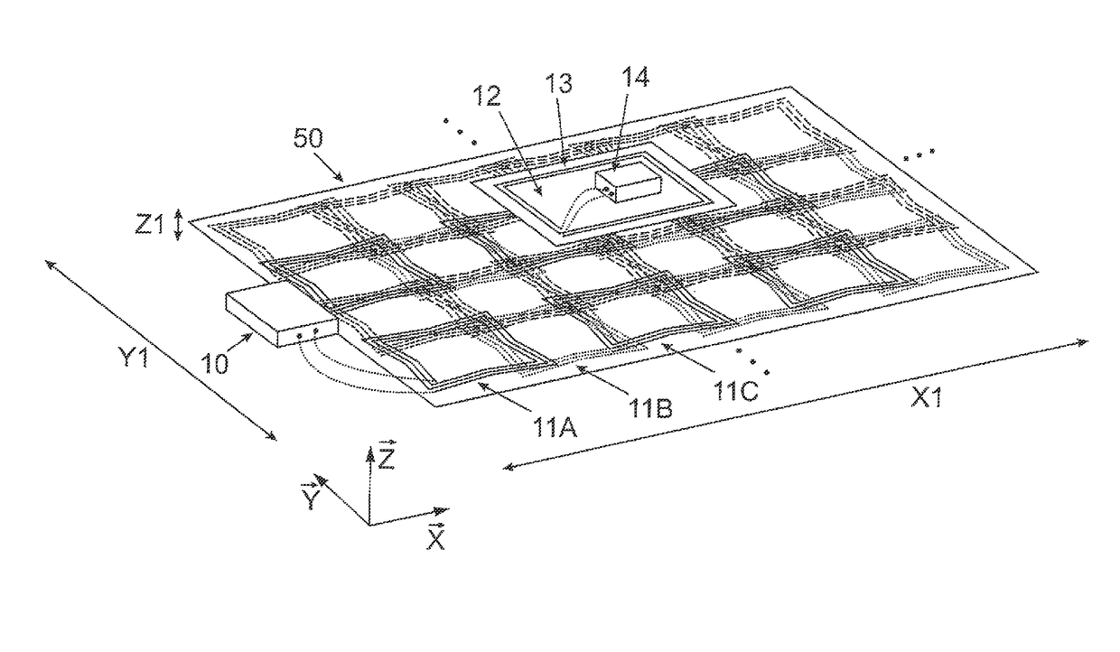
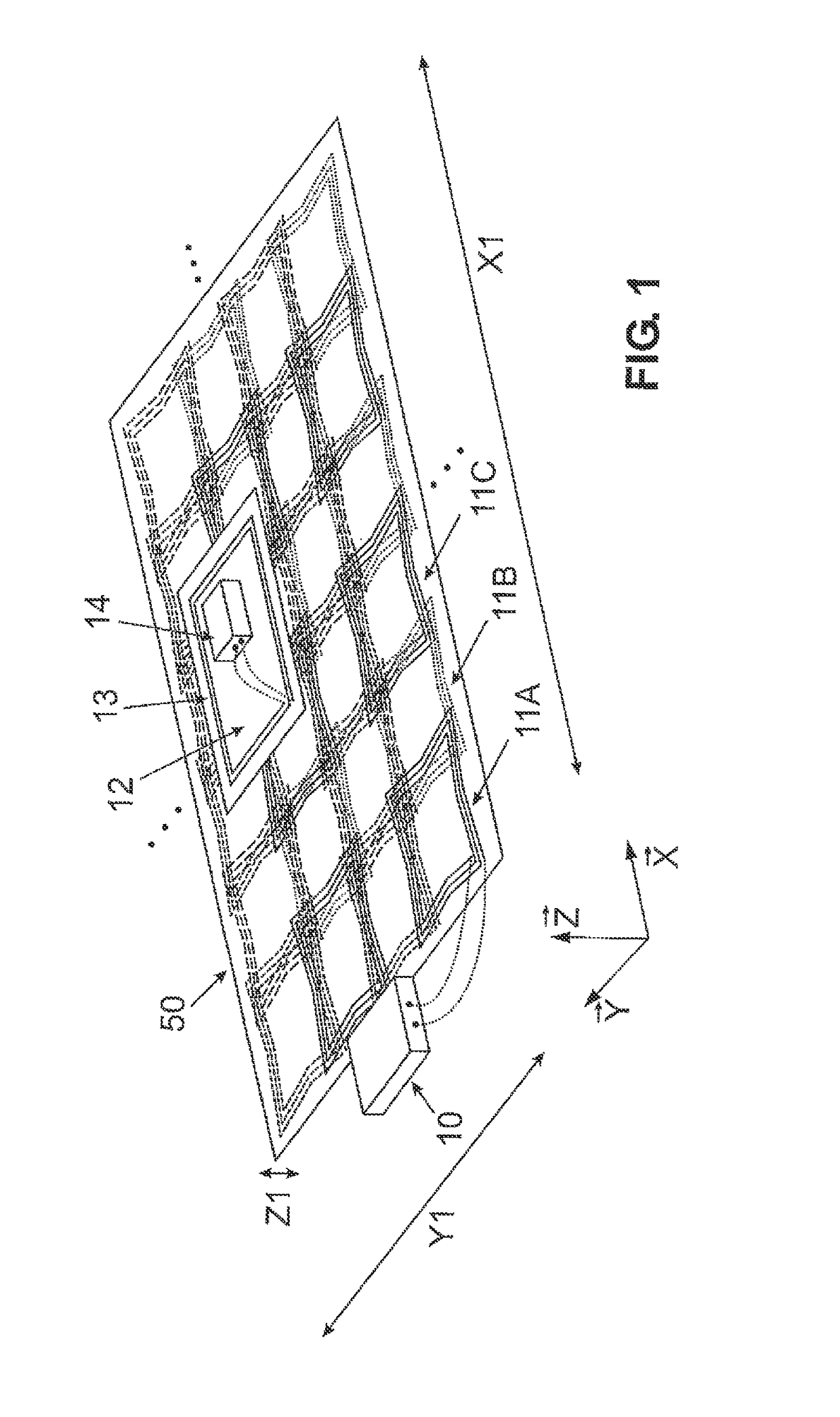
[0051]FIG. 1 is a perspective elevation of a first exemplary embodiment of the invention. It depicts an inventive coupling-minimized matrix made of transmitter coils 11A, 11B, 11C, . . . for inductive energy transmission. The flat layer or planar unit 50 is formed by a planar transmitter unit that comprises the transmitter coils 11A, 11B, 11C, etc. and a power supply 10 that is connected to all of the transmitter coils (illustrated only for coil 11A). The geometry of the transmitter coils is inventively optimized such that the mutual electromagnetic coupling of all transmitter coils to one another is minimized. This enables individual layout and control of the individual transmitter coils. One receiver 12, depicted as an example, is equipped with a receiver coil 13 that is connected to a receiving unit 14. The goal of this arrangement is the optimized inductive (contactless or wireless) transmission of energy from the planar unit 50 to the receiver 12. The position of the receiver 1...


PUM

PropertyMeasurementUnit
anglesaaaaaaaaaa
distanceaaaaaaaaaa
side lengthaaaaaaaaaa

Abstract

The invention relates to an arrangement and a method for contactless energy transmission by means of induction. There are a plurality of coils arranged in a matrix, the coils having at least one conductor that surrounds a central axis of the coil at least once in one turn. The central axis stands vertically on the surface surrounded by the conductor in the geometric center of area of the surrounded surface. The coils are arranged adjacent to one another in a planar unit that extends in a first dimension, in a second dimension, and in a third dimension. The extension of the planar unit in the first dimension and in the second dimension is significantly greater than in the third dimension. The central axis of each coil stands at least locally at least nearly perpendicular to the surface spanned by the first dimension and the second dimension. The coils are also arranged in a regular manner within the planar unit in rows and / or columns such that each coil has at least two or three immediately adjacent coils. The distances between geometric centers of area of the coils and the shape and the extension of the at least one turn per coil are selected such that the mutual electromagnetic coupling between coils is minimal for all pairs of immediately adjacent coils in the planar unit.

Description

FIELD OF THE INVENTION[0001]The invention relates to an arrangement and a method for inductive energy transmission with a coupling-minimized matrix of planar transmitter coils.BACKGROUND[0002]Contactless energy transmission systems based on induction are known in general. The principle is to use one or a plurality of transmitter or primary coils (also known as coils, conductor loops, turns, antennas, or current conductors) to generate voltage in one or a plurality of relatively closely positioned receiver or secondary coils by means of a temporally changeable current flux based on the principle of induction. The temporally changeable voltage induced in this manner in the receiver coil may then for instance be rectified and used to supply an electronic circuit with power and / or to charge a battery. There are numerous applications for this in consumer electronics, wherein mobile devices such as for instance laptops and smartphones are equipped with at least one integrated receiver coi...

Claims


Application Information

Patent Timeline
Patent Type & Authority Patents(United States)
IPC IPC(8): H01F38/14H02J50/10H02J50/40H02J7/02H04B5/00H02J7/00H02J50/70
CPCH01F38/14H02J7/0042H02J7/025H02J50/40H04B5/0037H04B5/0081H02J50/10H02J50/70
Inventor SCHOLZ, PETER-DOMINIKGALLIARDT, ARTJOM
Owner PHOENIX CONTACT GMBH & CO KG
Why Eureka
Try Eureka