
Electric connection box and wire harness

a technology of electric connection box and wire harness, which is applied in the direction of insulated conductors, cables, conductors, etc., can solve the problems of interrupting the power supply to the load side, and achieve the effect of improving the accuracy of circuit protection components

Active Publication Date: 2018-04-24
YAZAKI CORP
View PDF21 Cites 0 Cited by
  • Summary
  • Abstract
  • Description
  • Claims
  • Application Information

AI Technical Summary

Benefits of technology

The technical effect of this patent is to improve the accuracy of a circuit protection component in an electric connection box and wire harness.

Problems solved by technology

When a current equal to or larger than a predetermined value flows, this circuit protection component fuses a fuse element by self-heating, and interrupts power supply to the load side.

Method used


Image

  • Electric connection box and wire harness
  • Electric connection box and wire harness
  • Electric connection box and wire harness

Examples


embodiment

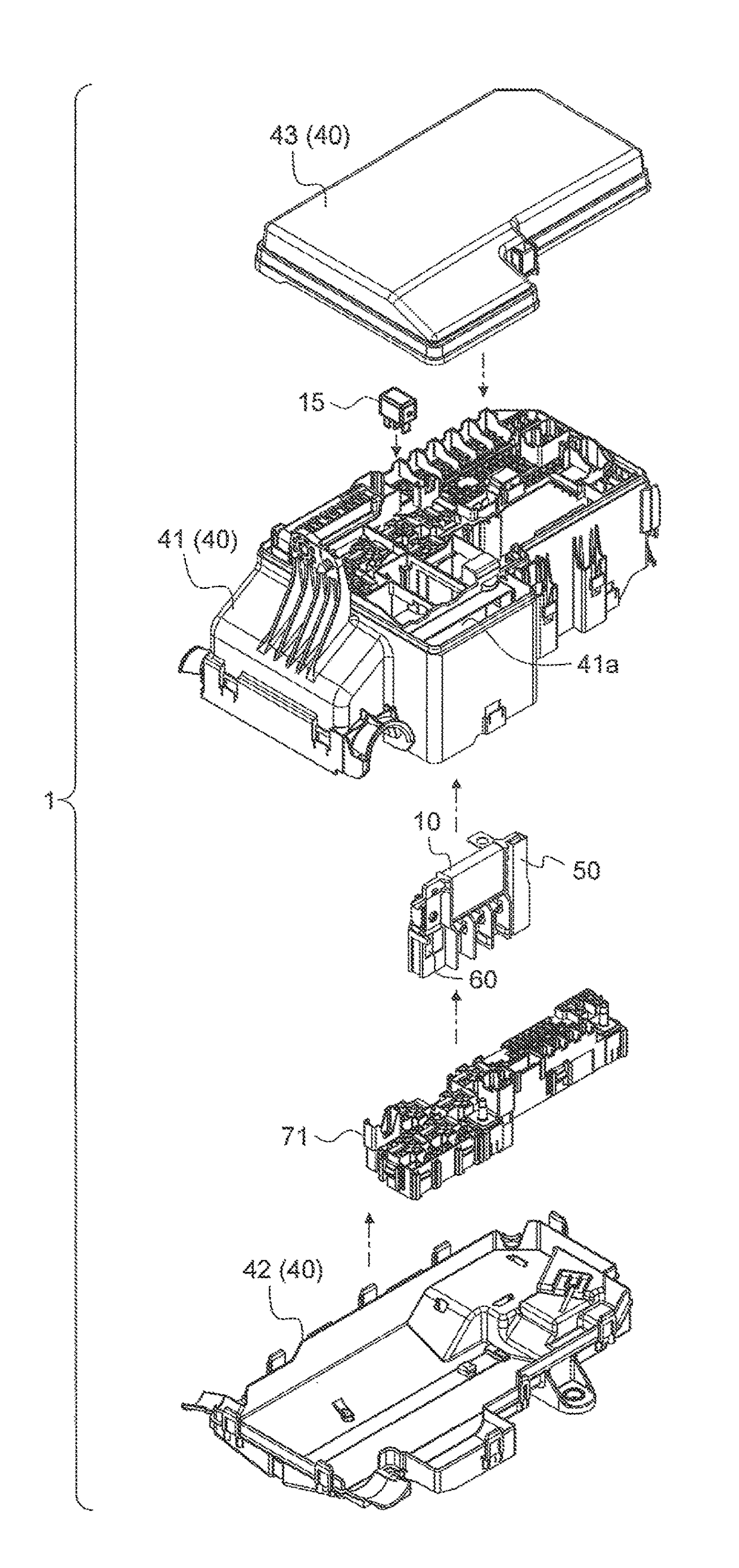
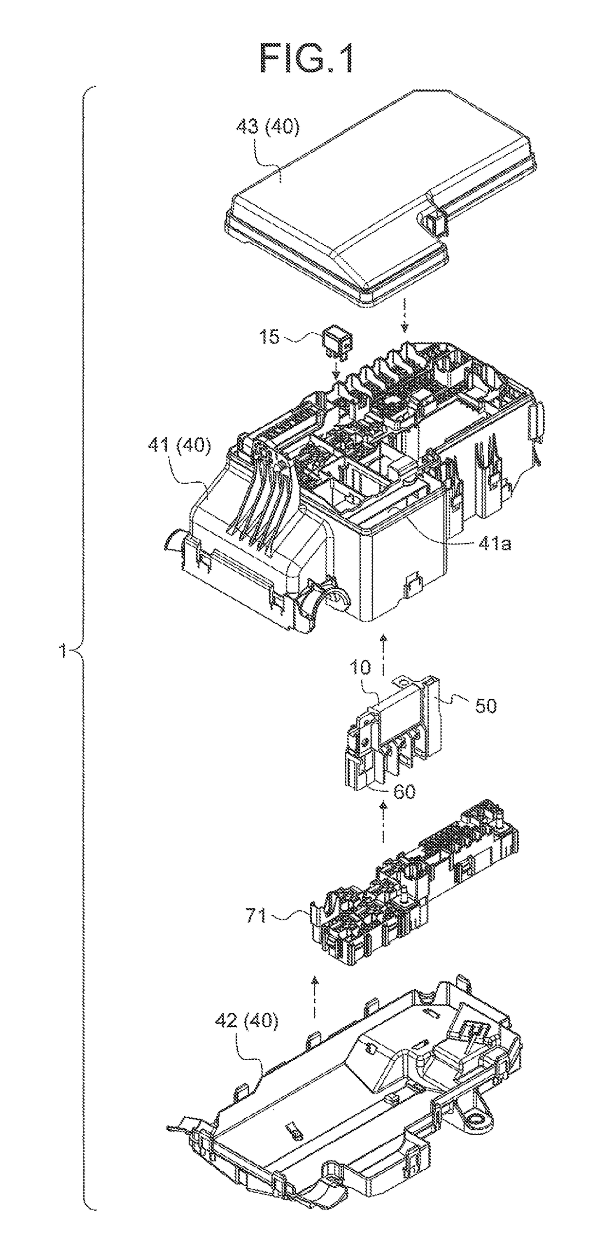
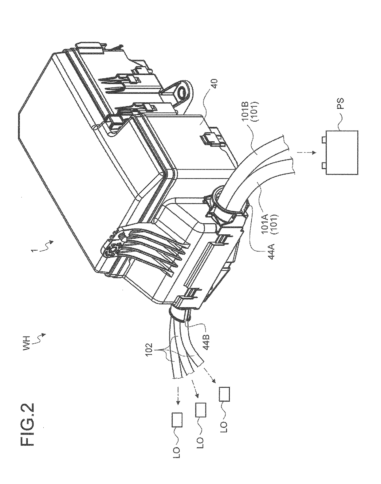
[0027]An embodiment of an electric connection box and a wire harness according to the present invention will be described with reference to FIGS. 1 to 13.

[0028]A numeral 1 in FIGS. 1 and 2 denotes an electric connection box in the embodiment. A symbol WH in FIG. 2 denotes a wire harness including the electric connection box 1.

[0029]The electric connection box 1 in the embodiment is interposed between a power supply (secondary battery) PS and a load LO, and includes at least a circuit protection component 10 for protecting an electric circuit between the power supply PS and the load LO. Examples of the circuit protection component 10 include a fuse and a fusible link. The electric connection box 1 may be referred to as a fuse box when the box does not include electric system components (except for electric wires) other than the circuit protection component 10.

[0030]Electric wires connected to the power supply PS side (hereinafter, referred to as “power supply side electric wires”) 10...


PUM

PropertyMeasurementUnit
heat conductiveaaaaaaaaaa
currentaaaaaaaaaa
temperatureaaaaaaaaaa

Abstract

An electric connection box includes a circuit protection component, a housing, and a metal heat conductive member. The circuit protection component is provided with a metal circuit protection member. The circuit protection member includes a power supply side connector that is electrically connected to power supply side electric wires connected to a power supply side, load side connectors that are electrically connected to load side electric wires connected to a load side, and fuse elements interposed between the power supply side connector and the load side connectors. The housing is formed of an insulating material, and includes a protection component holding unit that holds the circuit protection component. The heat conductive member includes a contacting portion that contacts the power supply side connector in a state where the protection component holding unit holds the circuit protection component, and a heat conducting portion connected to the contacting portion.

Description

CROSS-REFERENCE TO RELATED APPLICATION(S)[0001]The present application claims priority to and incorporates by reference the entire contents of Japanese Patent Application No. 2015-109443 filed in Japan on May 29, 2015.BACKGROUND OF THE INVENTION1. Field of the Invention[0002]The present invention relates to an electric connection box and a wire harness.2. Description of the Related Art[0003]Conventionally, there have been known an electric connection box disposed between a power supply and a plurality of loads installed in a vehicle, and a wire harness including the electric connection box. As an example of the electric connection box, there has been known an electric connection box including a circuit protection component such as a fusible link. The circuit protection component is provided with a metal circuit protection member including a fuse element, and is connected to an electric wire on a power supply side and an electric wire on a load side while this fuse element is interpo...

Claims


Application Information

Patent Timeline
Patent Type & Authority Patents(United States)
IPC IPC(8): H01H85/20H01H85/04H01B7/00H01H85/02
CPCH01H85/20H01H85/0241H01H2085/208
Inventor IKEDA, TATSUHIKOKAKIMI, TAKAAKI
Owner YAZAKI CORP
Learn More