
High-precision current/frequency conversion circuit and conversion method based on triangular wave modulation

A frequency conversion circuit, triangular wave technology, applied in the direction of pulse duration/width modulation, electrical components, pulse generation, etc., can solve the problems of large switching times of constant current source, large debugging workload, high component requirements, etc. It is difficult to debug, improve the accuracy of the circuit, and reduce the effect of errors

Pending Publication Date: 2018-12-14
NO 43 INST OF CHINA ELECTRONICS TECH GRP CETC
View PDF0 Cites 6 Cited by
  • Summary
  • Abstract
  • Description
  • Claims
  • Application Information

AI Technical Summary

Problems solved by technology

At present, the current / frequency conversion circuit using the principle of charge balance is widely used. In the traditional method, the threshold level compared with the main integrator adopts a fixed threshold level. When the input current signal is large, the number of constant current source switching is relatively large. Since the transition time in the switching process of the constant current source is the main factor affecting the conversion accuracy, its accuracy is difficult to achieve the ideal target, and compensation or digital calibration methods are usually used to compensate, but the process is complicated, the debugging workload is heavy, and the requirements for components are high.

Method used


Image

  • High-precision current/frequency conversion circuit and conversion method based on triangular wave modulation
  • High-precision current/frequency conversion circuit and conversion method based on triangular wave modulation
  • High-precision current/frequency conversion circuit and conversion method based on triangular wave modulation

Examples


Embodiment Construction

[0020] The present invention will be further described below in conjunction with accompanying drawing:

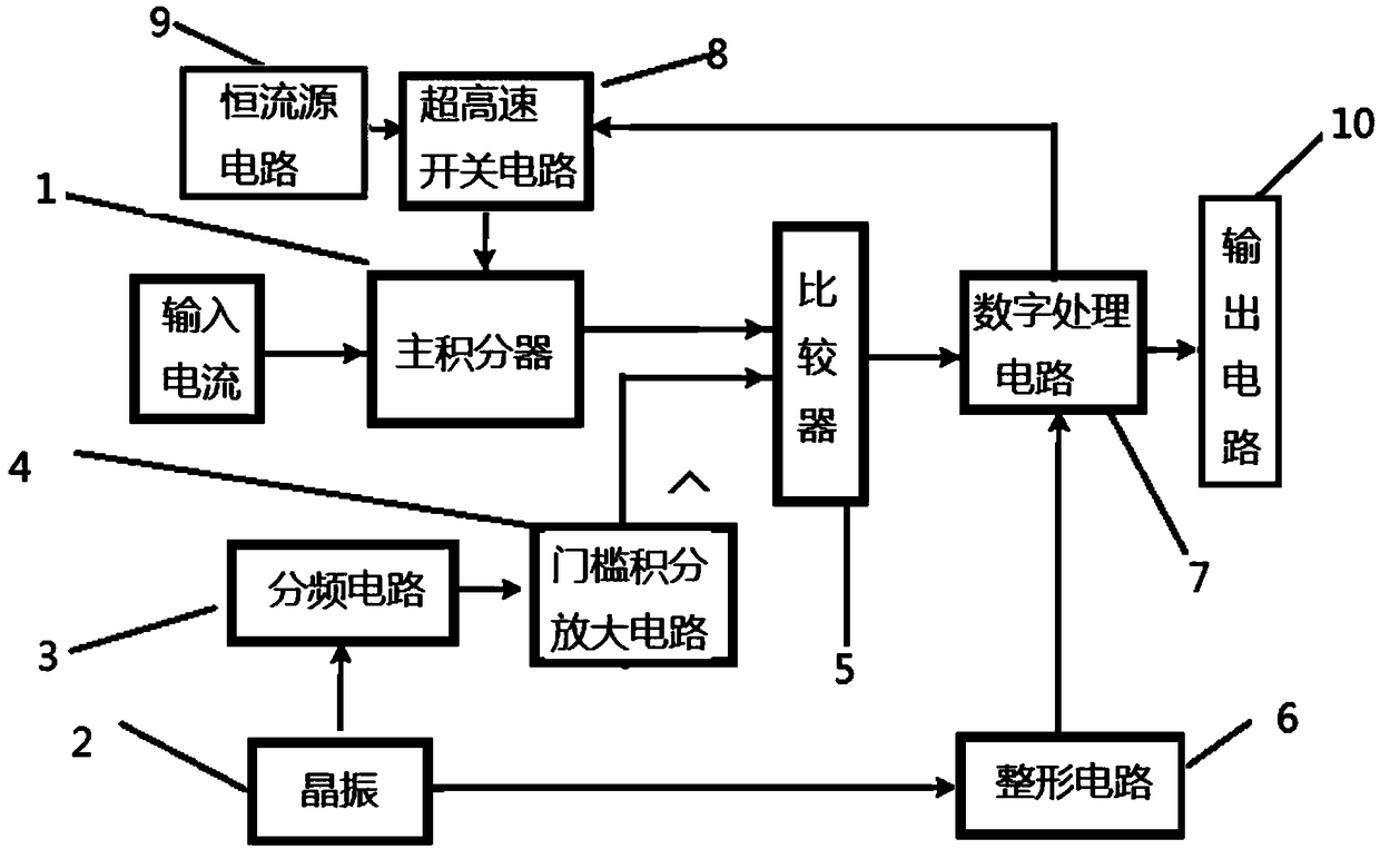
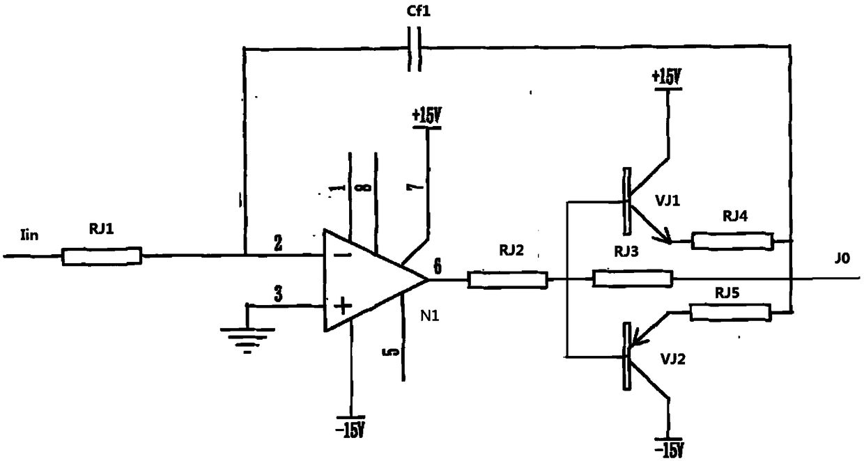
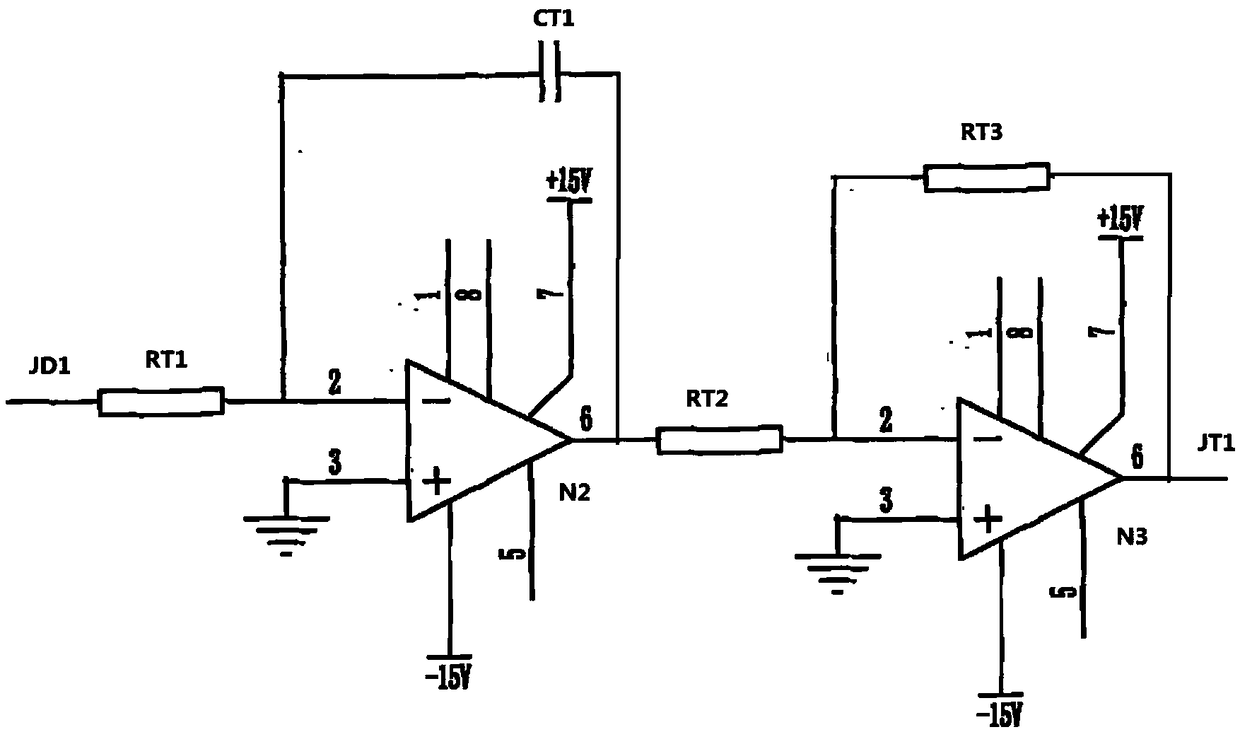
[0021] Such as figure 1 As shown, the high-precision current / frequency conversion circuit based on triangular wave modulation in this embodiment includes a main integrator 1, a comparator 5, a digital processing circuit 7, a shaping circuit 6, an ultra-high-speed switching circuit 8, a constant current source circuit 9, The output circuit 10 and the triangular wave generating circuit, the input end of the main integrator 1 is the input current end, the output end of the main integrator 1 and the triangular wave generating circuit is connected with the input end of the comparator 5, and the output end of the comparator 5 is connected with the digital processing circuit One input terminal of 7 is connected, and two output terminals of digital processing circuit 7 are respectively connected with the control terminal of ultra-high-speed switch circuit 8 and the input end of out...


PUM


Abstract

The invention relates to a high-precision current / frequency conversion circuit and a conversion method based on triangular wave modulation, the high-precision current / frequency conversion circuit includes a main integrator, the input terminal of the main integrator is an input current terminal, the output terminals of the main integrator and the triangular wave generating circuit are connected with the input terminal of the comparator, the output of the comparator is connected to one input of the digital processing circuit, the two output terminals of the digital processing circuit are respectively connected with the control terminal of the ultra-high speed switching circuit and the input end of the output circuit, the input end of the ultra-high speed switching circuit is connected with the output end of the constant current source circuit, the output end of the ultra-high speed switching circuit is connected with the input end of the main integrator, the output end of the shaping circuit is connected with the other input end of the digital processing circuit, and the input end of the shaping circuit is connected with the output end of the triangular wave generating circuit. The invention solves the problems that the debugging is difficult in the current production debugging process, the debugging personnel are required to be high, and the batch production demand cannot be met.

Description

technical field [0001] The technical field of the analog-digital hybrid circuit of the present invention specifically relates to a high-precision current / frequency conversion circuit and a conversion method based on triangular wave modulation. Background technique [0002] The current / frequency conversion circuit is one of the important components of the inertial navigation system. It is used together with the accelerometer in the inertial navigation system to convert the output current of the accelerometer into a digital pulse signal proportional to it. At present, the current / frequency conversion circuit using the principle of charge balance is widely used. In the traditional method, the threshold level compared with the main integrator adopts a fixed threshold level. When the input current signal is large, the number of constant current source switching is relatively large. Since the transition time in the switching process of the constant current source is the main facto...

Claims


Application Information

Patent Timeline
IPC IPC(8): H03K4/502H03K7/08
CPCH03K4/502H03K7/08Y02B70/10
Inventor 汪金华倪敏尚玉凤庄永河李鸿高
Owner NO 43 INST OF CHINA ELECTRONICS TECH GRP CETC
Learn More